Copyright
©The Author(s) 2025.
World J Radiol. Nov 28, 2025; 17(11): 113153
Published online Nov 28, 2025. doi: 10.4329/wjr.v17.i11.113153
Published online Nov 28, 2025. doi: 10.4329/wjr.v17.i11.113153
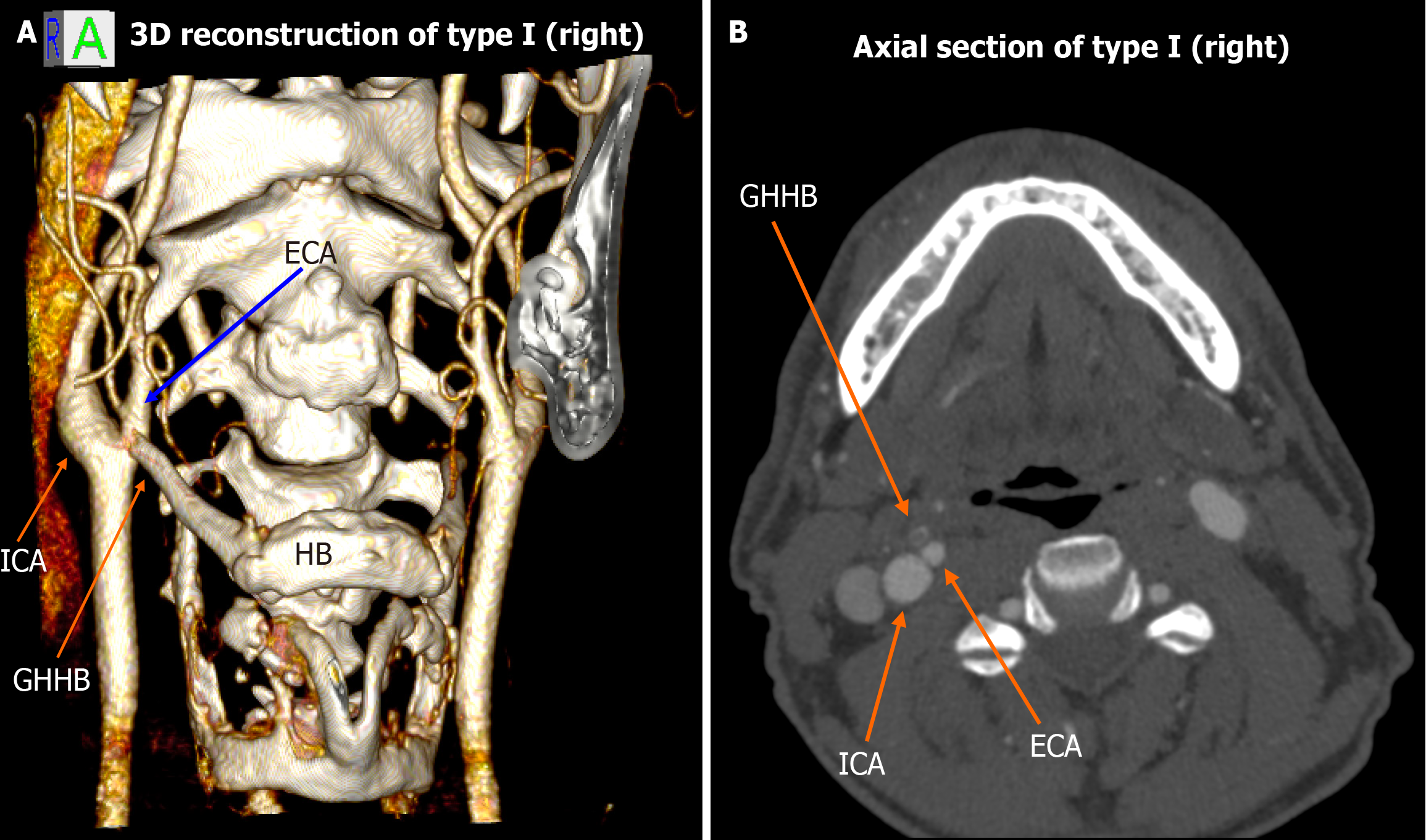
Figure 1 Type I spatial configuration (right-sided).
A: 3D volume rendering shows the external carotid artery medial to the greater horn of the hyoid bone, while the internal carotid artery remains lateral; B: Corresponding axial computed tomography angiography slice confirming the same relationship. ECA: External carotid artery; GHHB: Greater horn of the hyoid bone; HB: Hyoid bone; ICA: Internal carotid artery.
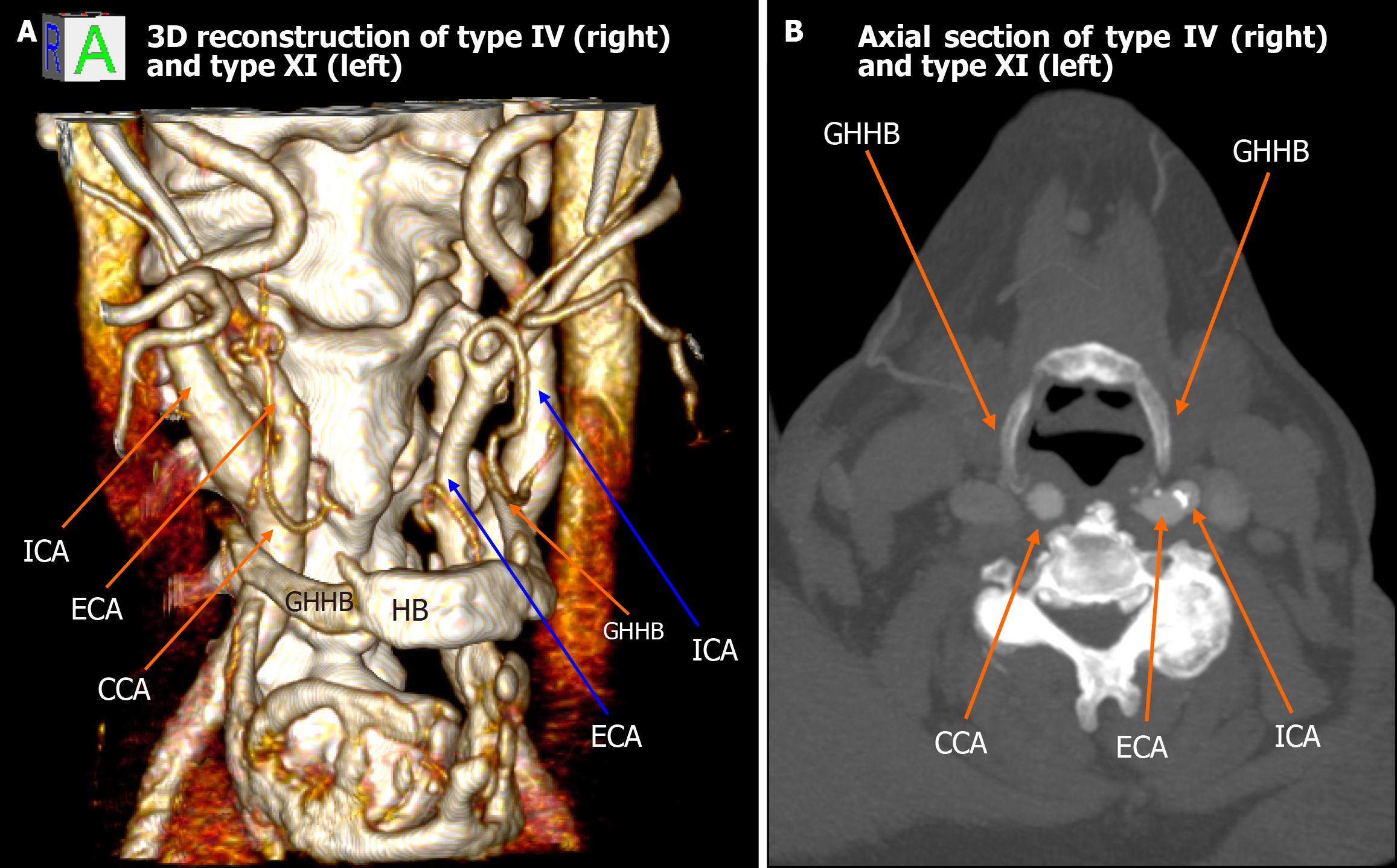
Figure 2 Type IV (right) and type XI (left) configuration.
A: 3D reconstruction shows the right common carotid artery positioned medial to the greater horn of hyoid bone (type IV) and the left external carotid artery lateral with internal carotid artery medial to greater horn of hyoid bone (type XI); B: Axial computed tomography images confirm the asymmetric carotid-hyoid relationships. ICA: Internal carotid artery; ECA: External carotid artery; CCA: Common carotid artery; GHHB: Greater horn of hyoid bone; HB: Hyoid bone.
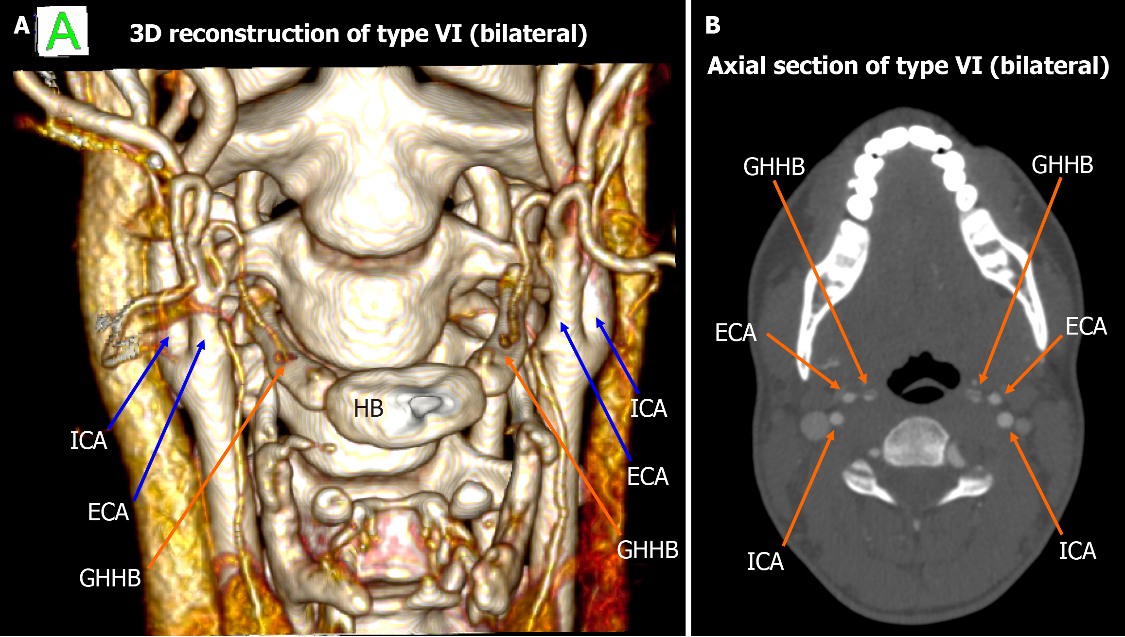
Figure 3 Type VI bilateral configuration.
A: 3D reconstruction shows the external carotid arteries bilaterally lateral to the greater horn of hyoid bone; B: The axial view demonstrates the symmetry of this type VI pattern. ICA: Internal carotid artery; ECA: External carotid artery; GHHB: Greater horn of hyoid bone; HB: Hyoid bone.
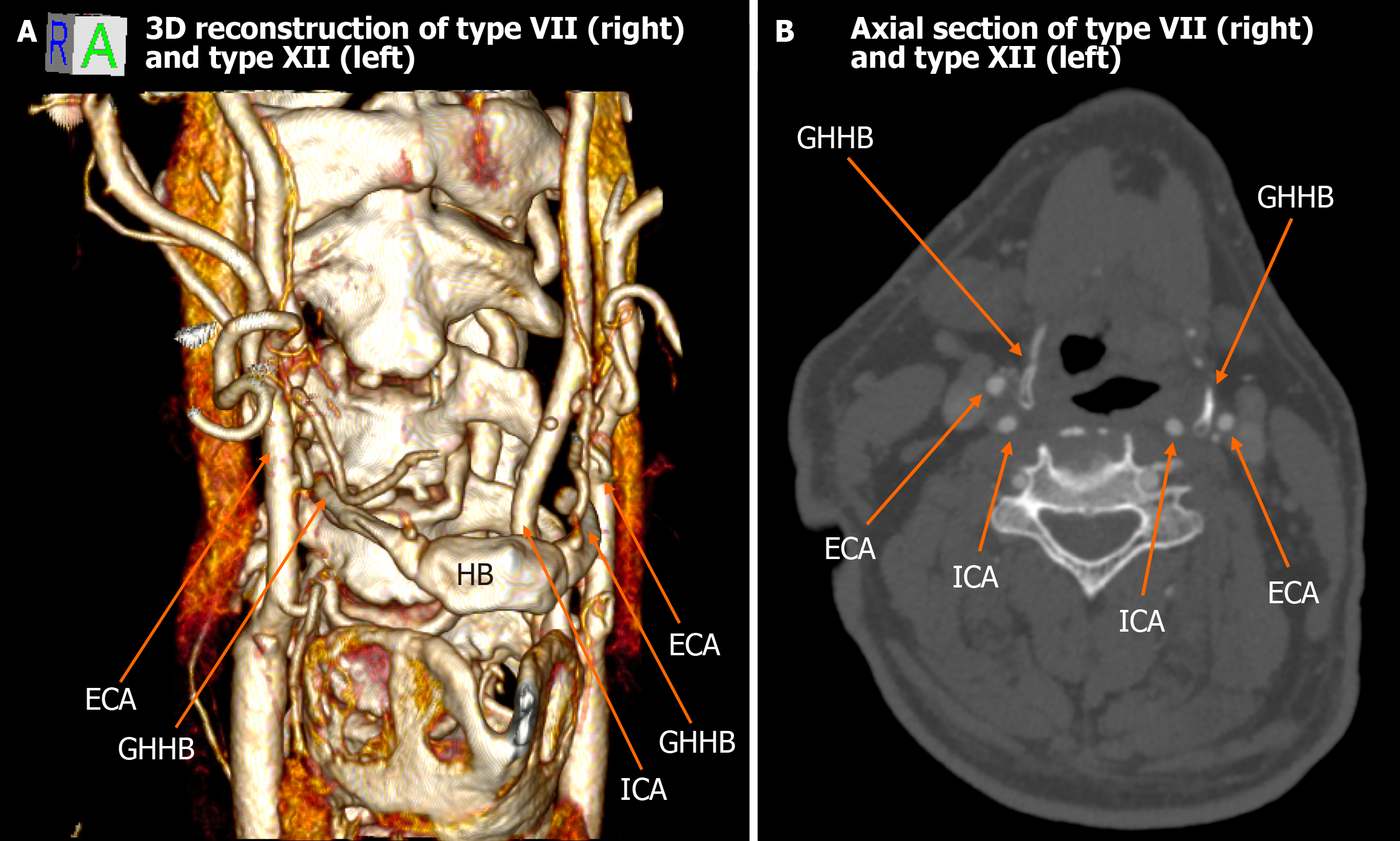
Figure 4 Type VII (right) and type XII (left).
A: The 3D rendering reveals that the right external carotid artery and internal carotid artery are both located lateral to the greater horn of hyoid bone (type VII), whereas on the left, the external carotid artery is medial, and the internal carotid artery is lateral to the greater horn of hyoid bone (type XII); B: Axial computed tomography confirms the described relationships. ICA: Internal carotid artery; ECA: External carotid artery; GHHB: Greater horn of hyoid bone; HB: Hyoid bone.
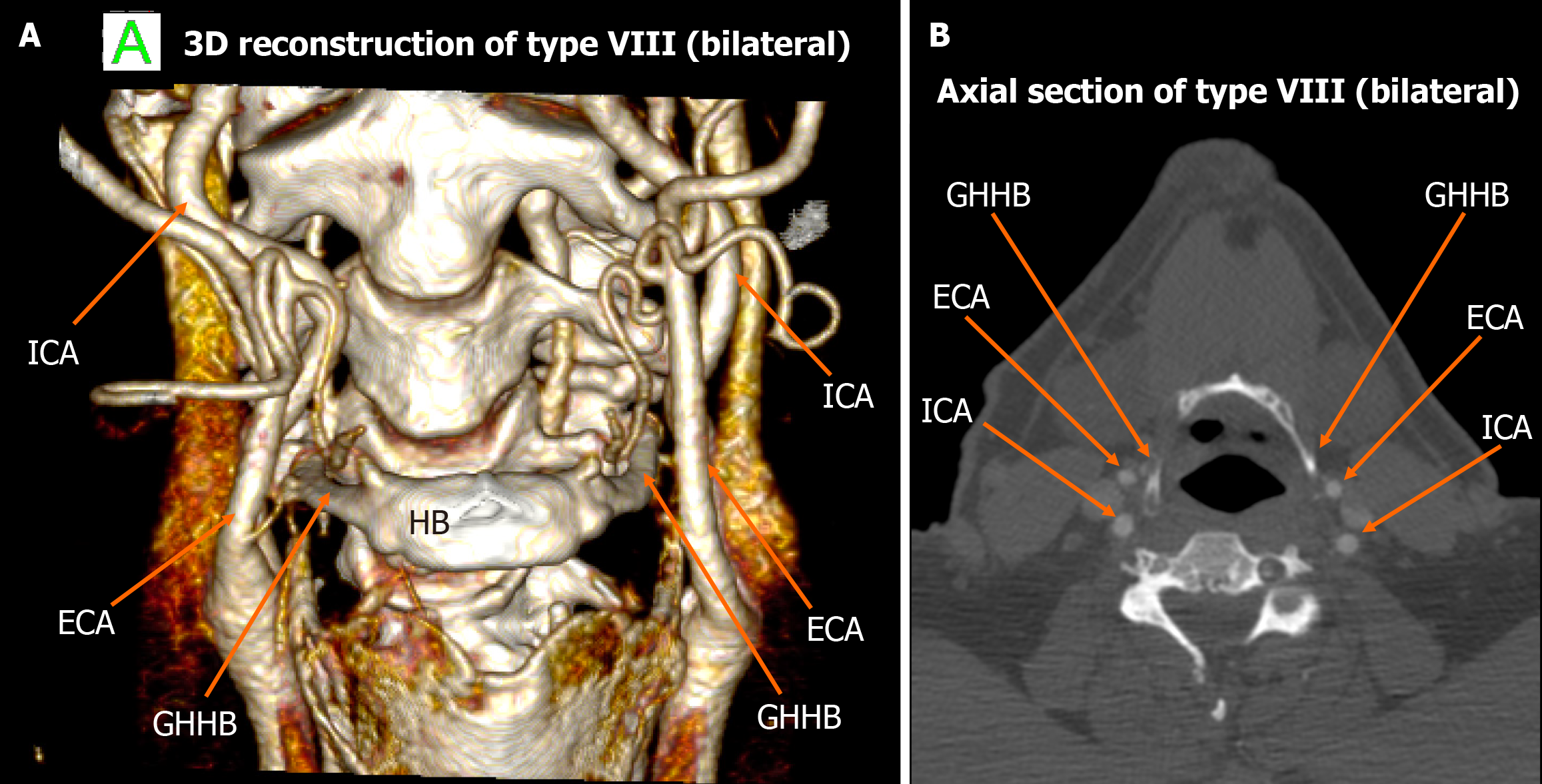
Figure 5 Type VIII bilateral configuration.
A: 3D volume-rendered image depicts both internal carotid artery and external carotid artery lateral to the greater horn of hyoid bone bilaterally; B: Axial computed tomography angiography confirms this symmetric type VIII presentation. ICA: Internal carotid artery; ECA: External carotid artery; GHHB: Greater horn of hyoid bone; HB: Hyoid bone.
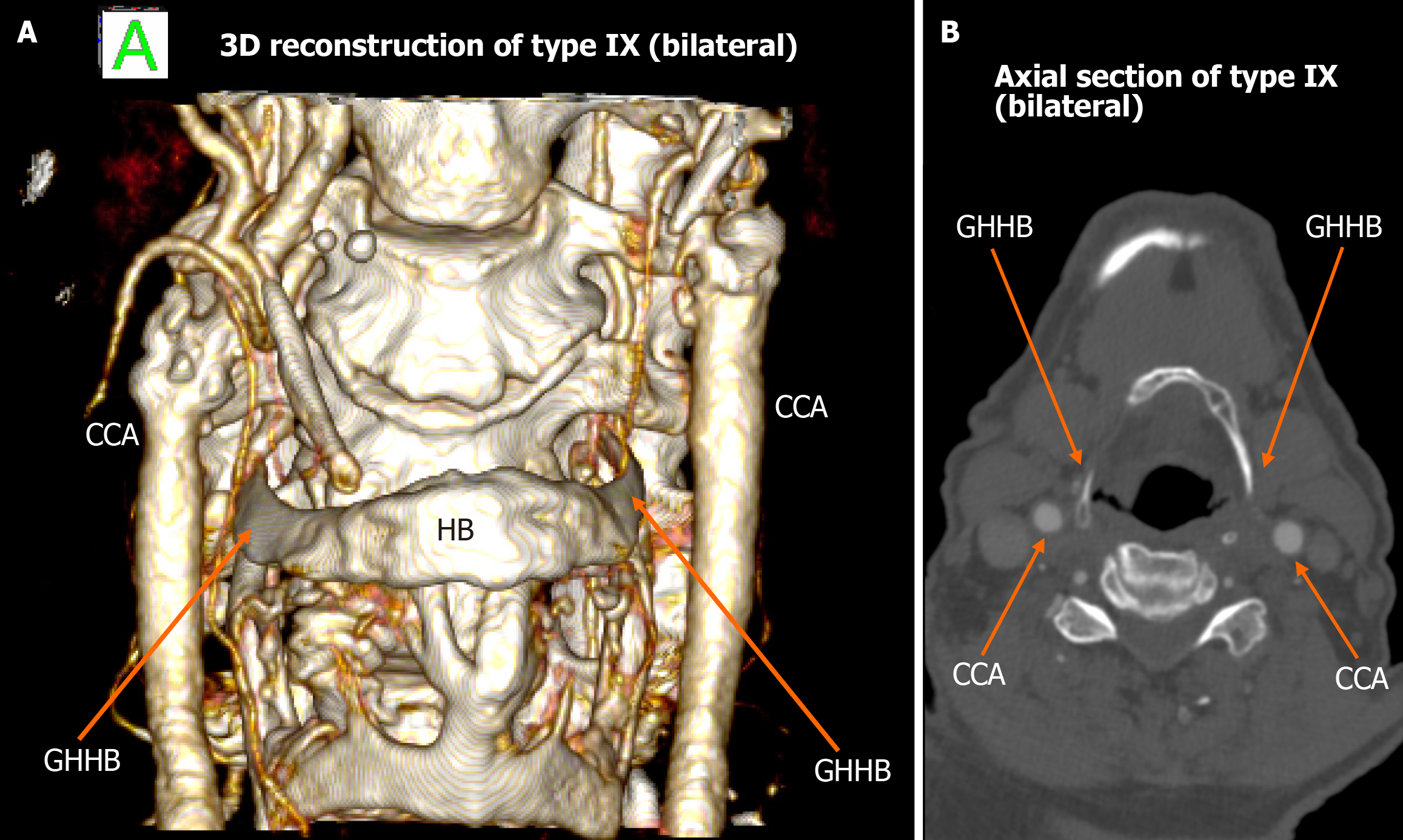
Figure 6 Type IX bilateral configuration.
A: 3D reconstruction shows the internal carotid artery positioned medially to the greater horn of hyoid bone on both sides; B: Axial computed tomography angiography illustrates bilateral type IX anatomy. ICA: Internal carotid artery; GHHB: Greater horn of hyoid bone; HB: Hyoid bone; CCA: Common carotid artery.
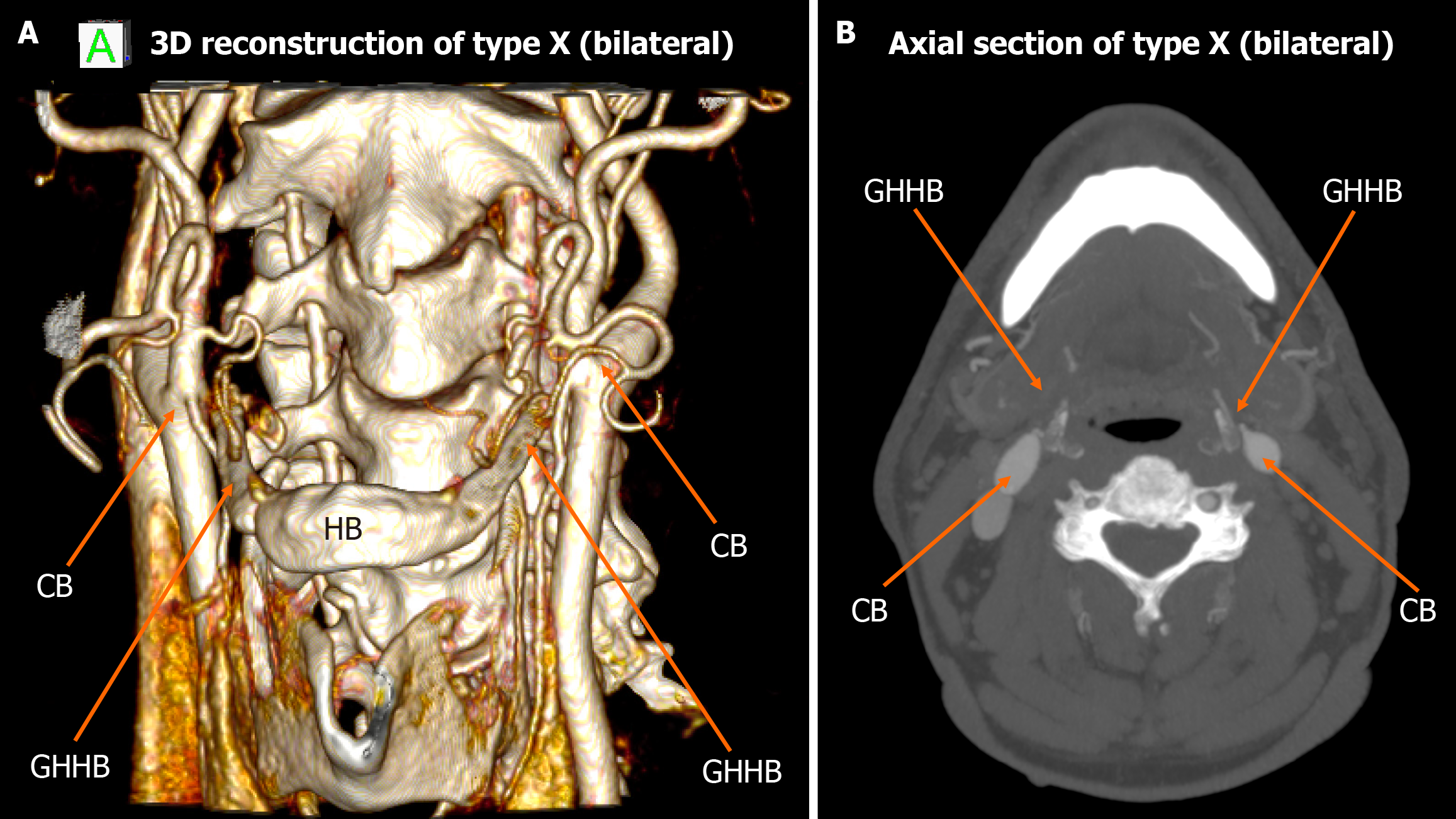
Figure 7 Type X bilateral configuration.
A: 3D reconstruction demonstrating the carotid bifurcation located lateral to the greater horn of hyoid bone on both sides; B: Axial view highlights bilateral type X relationship. CB: Carotid bifurcation; GHHB: Greater horn of hyoid bone; HB: Hyoid bone.
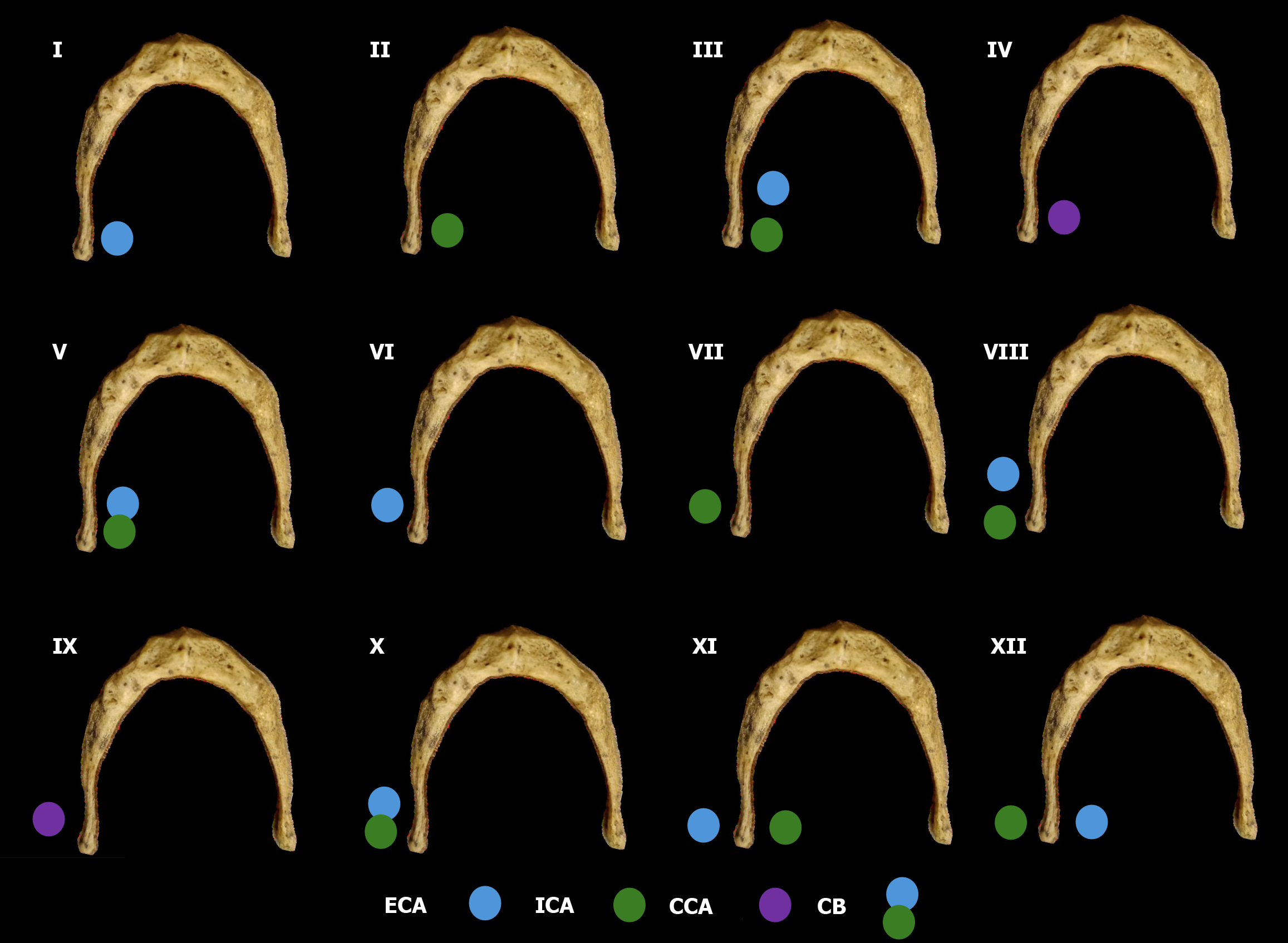
Figure 8 Schematic representation of all topographical patterns between the external carotid artery, internal carotid artery or common carotid artery with the hyoid bone.
ICA: Internal carotid artery; ECA: External carotid artery; CCA: Common carotid artery; CB: Carotid bifurcation.
- Citation: Karangeli N, Triantafyllou G, Papadopoulos-Manolarakis P, Arkoudis NA, Velonakis G, Samolis A, Piagkou M. Variations in the spatial relationship between the hyoid bone and the carotid arteries and their clinical significance. World J Radiol 2025; 17(11): 113153
- URL: https://www.wjgnet.com/1949-8470/full/v17/i11/113153.htm
- DOI: https://dx.doi.org/10.4329/wjr.v17.i11.113153


