Copyright
©The Author(s) 2023.
World J Clin Cases. Jul 16, 2023; 11(20): 4814-4823
Published online Jul 16, 2023. doi: 10.12998/wjcc.v11.i20.4814
Published online Jul 16, 2023. doi: 10.12998/wjcc.v11.i20.4814
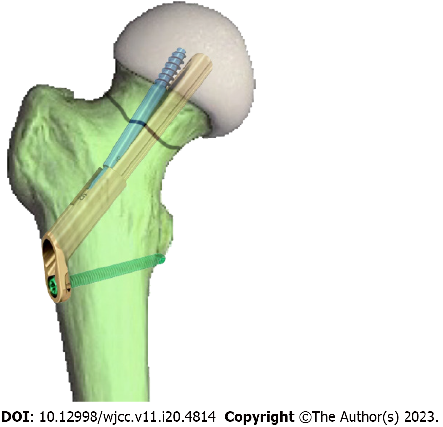
Figure 1
The femoral neck dynamic intersection system for femoral neck fracture fixation.
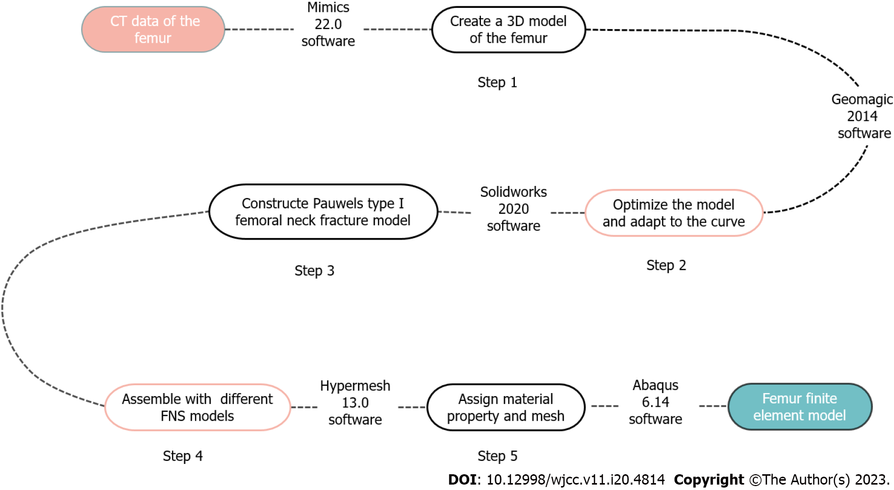
Figure 2 Flow chart of finite element model establishment.
CT: Computed tomography; 3D: Three-dimensional; FNS: Femoral neck dynamic intersection system.
Figure 3 Schematic diagram of femoral neck dynamic intersection system composition.
A: Lateral locking steel plate; B: Main nail; C: Anti-rotation screw; D: Locking nail.
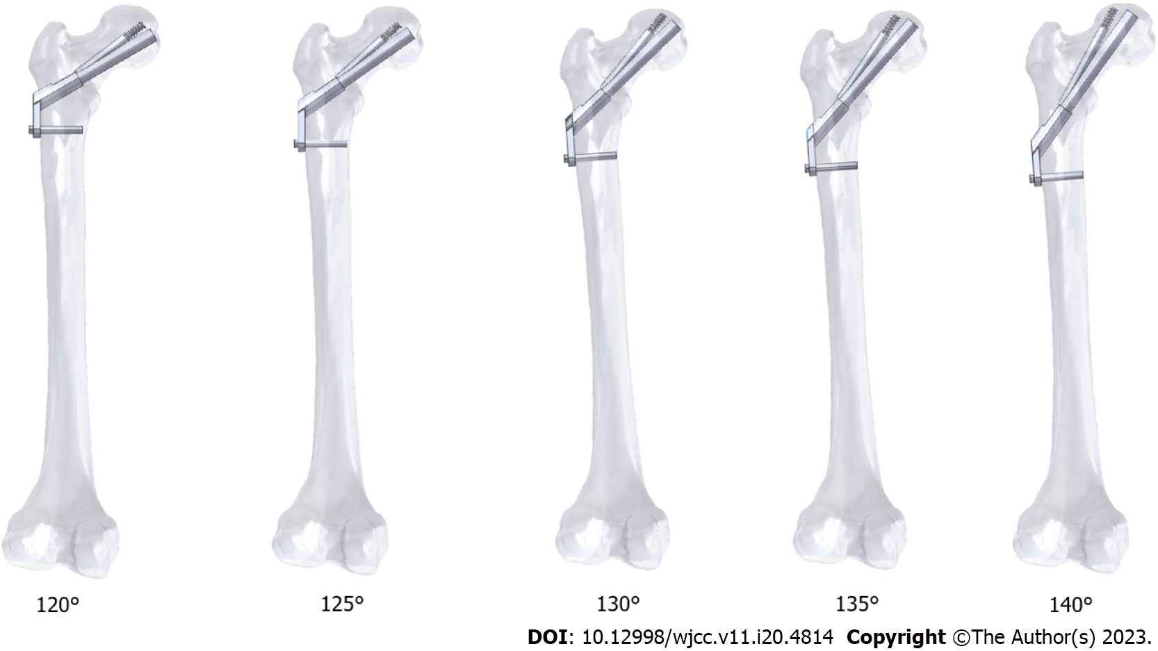
Figure 4
Schematic diagram of the femoral neck fracture model with different main nail angles for femoral neck dynamic intersection system fixation.
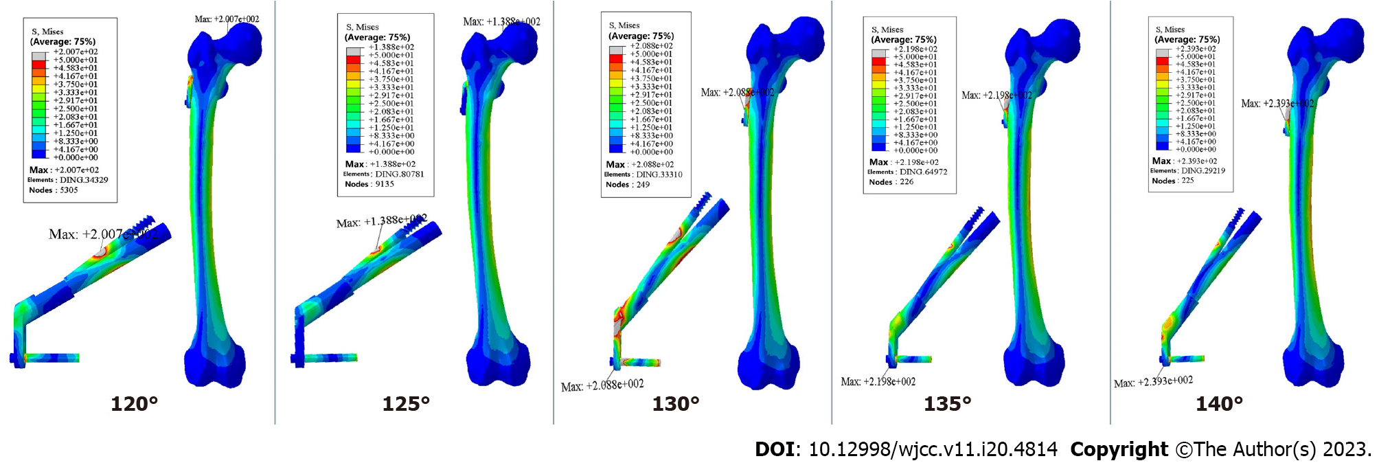
Figure 5
The Von Mises stress distribution and peak value for five angles of fixation of femoral neck fracture.
Figure 6
Von Mises stress distribution and peak value of the femoral head.
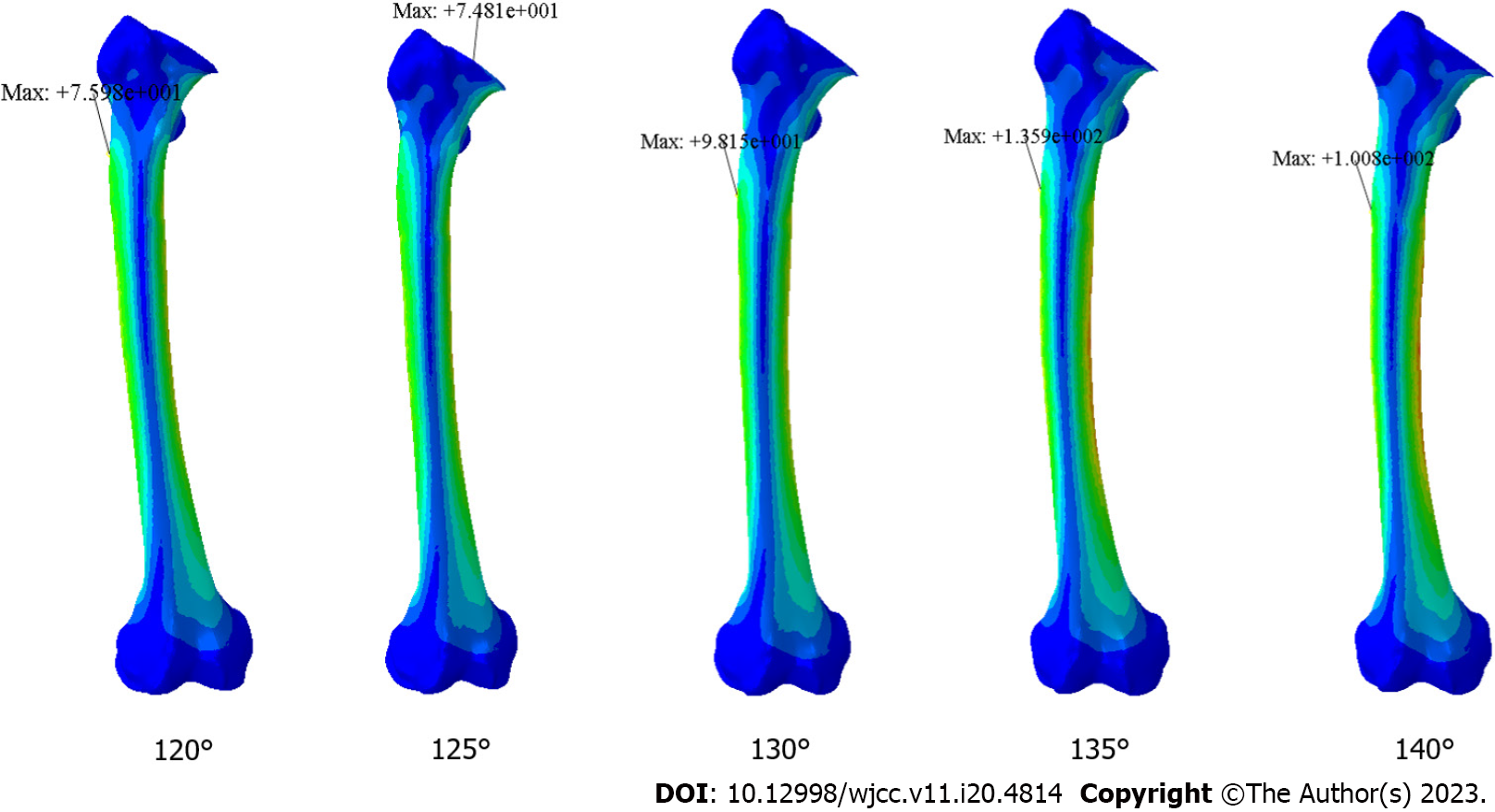
Figure 7
Femoral stress distribution and peak values.
- Citation: Wang Y, Ma JX, Bai HH, Lu B, Sun L, Jin HZ, Ma XL. Mechanical analysis of the femoral neck dynamic intersection system with different nail angles and clinical applications. World J Clin Cases 2023; 11(20): 4814-4823
- URL: https://www.wjgnet.com/2307-8960/full/v11/i20/4814.htm
- DOI: https://dx.doi.org/10.12998/wjcc.v11.i20.4814


