Copyright
©The Author(s) 2022.
World J Clin Cases. Jun 16, 2022; 10(17): 5816-5824
Published online Jun 16, 2022. doi: 10.12998/wjcc.v10.i17.5816
Published online Jun 16, 2022. doi: 10.12998/wjcc.v10.i17.5816
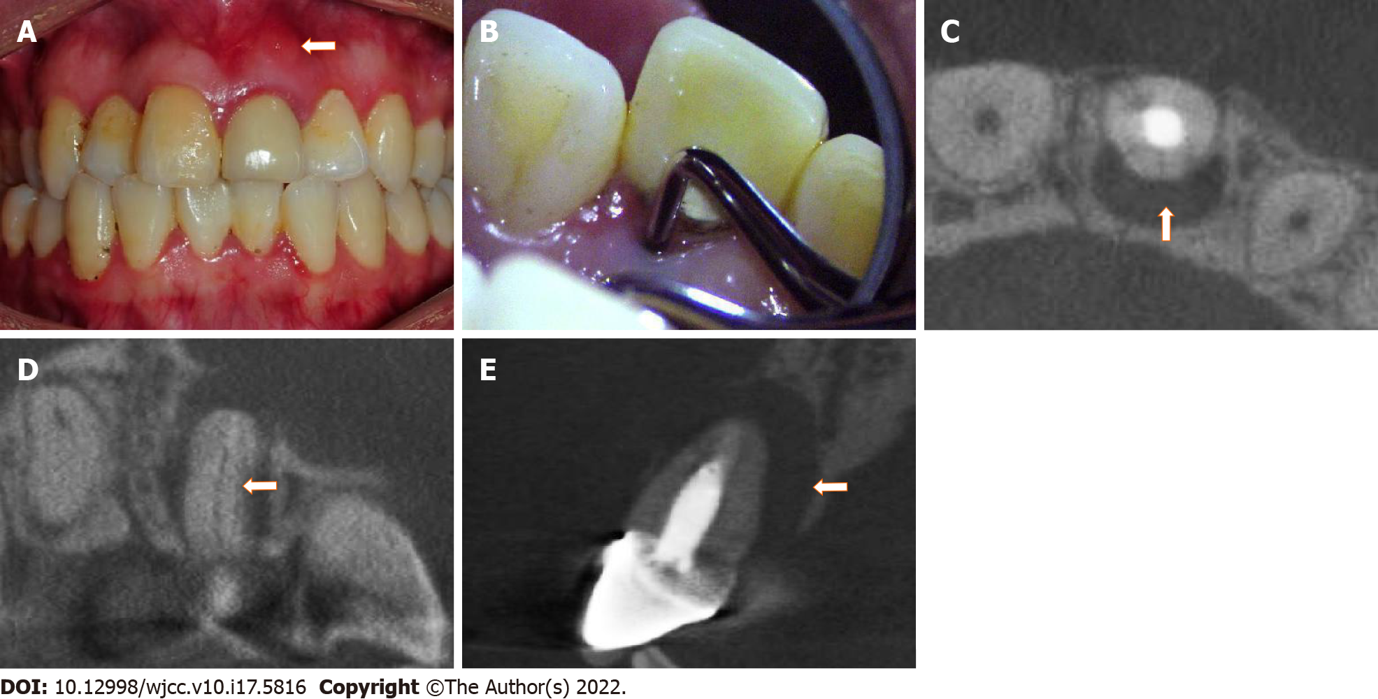
Figure 1 Preoperative images.
A: Sinus on the labial gingival mucosa near the apical region of tooth #9; B: Deep narrow isolated pocket on the palatal aspect of tooth #9; C: A cone beam computed tomography (CBCT) cross-sectional image showing a fracture line (arrowhead) on the palatal aspect of tooth #9; D: A CBCT coronal-section image showing a fracture line (arrowhead) from the cervical region to the apex; E: A CBCT sagittal-section image showing a large region of bone destruction (arrowhead) in the palatal and apical areas of the root.
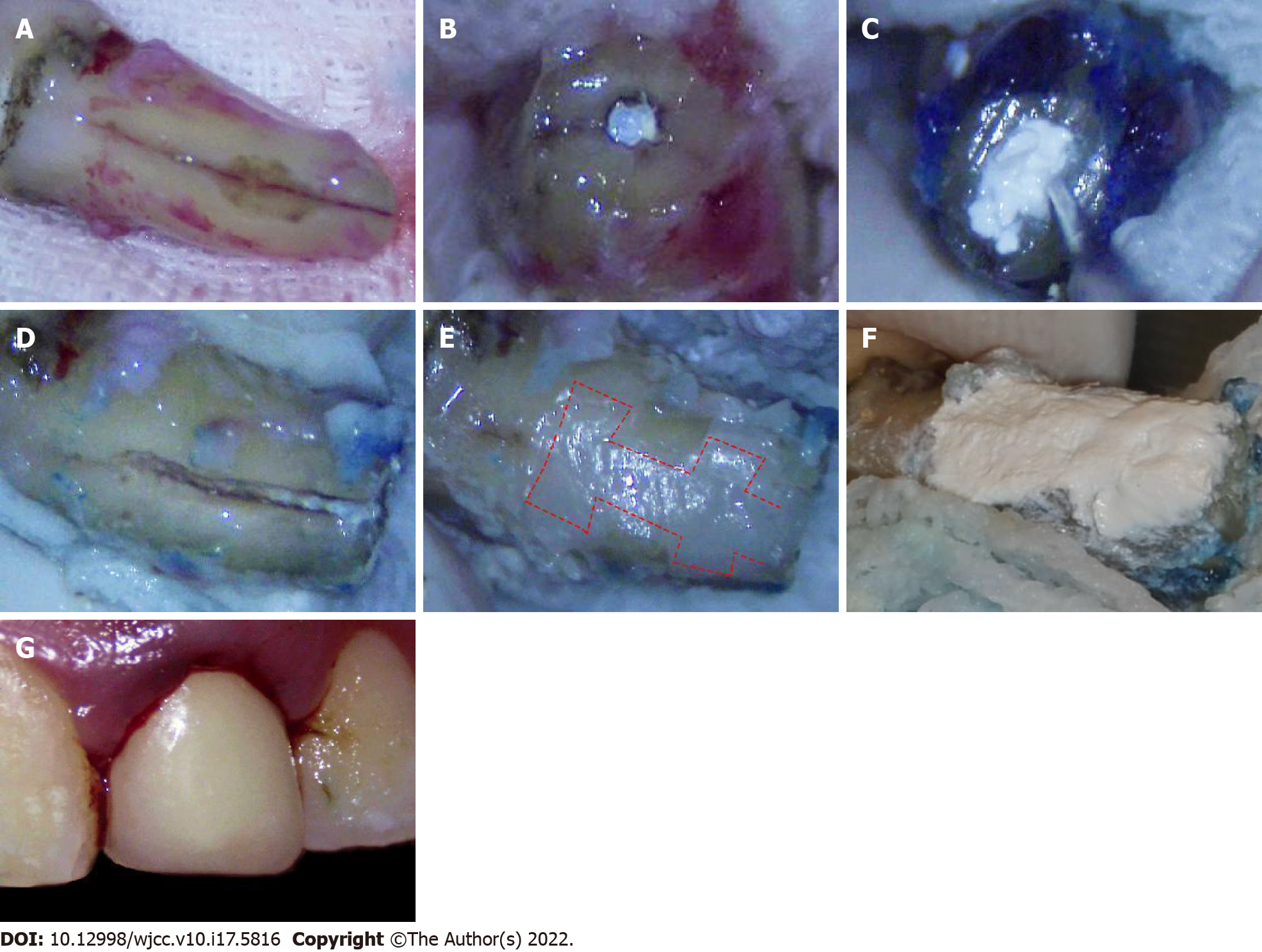
Figure 2 Operative images.
A: A vertical root fracture line after the granulation tissue was removed; B: Excision of the 3-mm apex; C: Filling of the retrograde canal with iRoot BP Plus after retrograde canal preparation; D: Cleaning and enlargement of the fracture line; E: Filling of the fracture and trapezoidal retention forms (shown by dotted line) with resin; F: Covering of the resin surface with iRoot BP Plus; G: Replantation of the tooth.
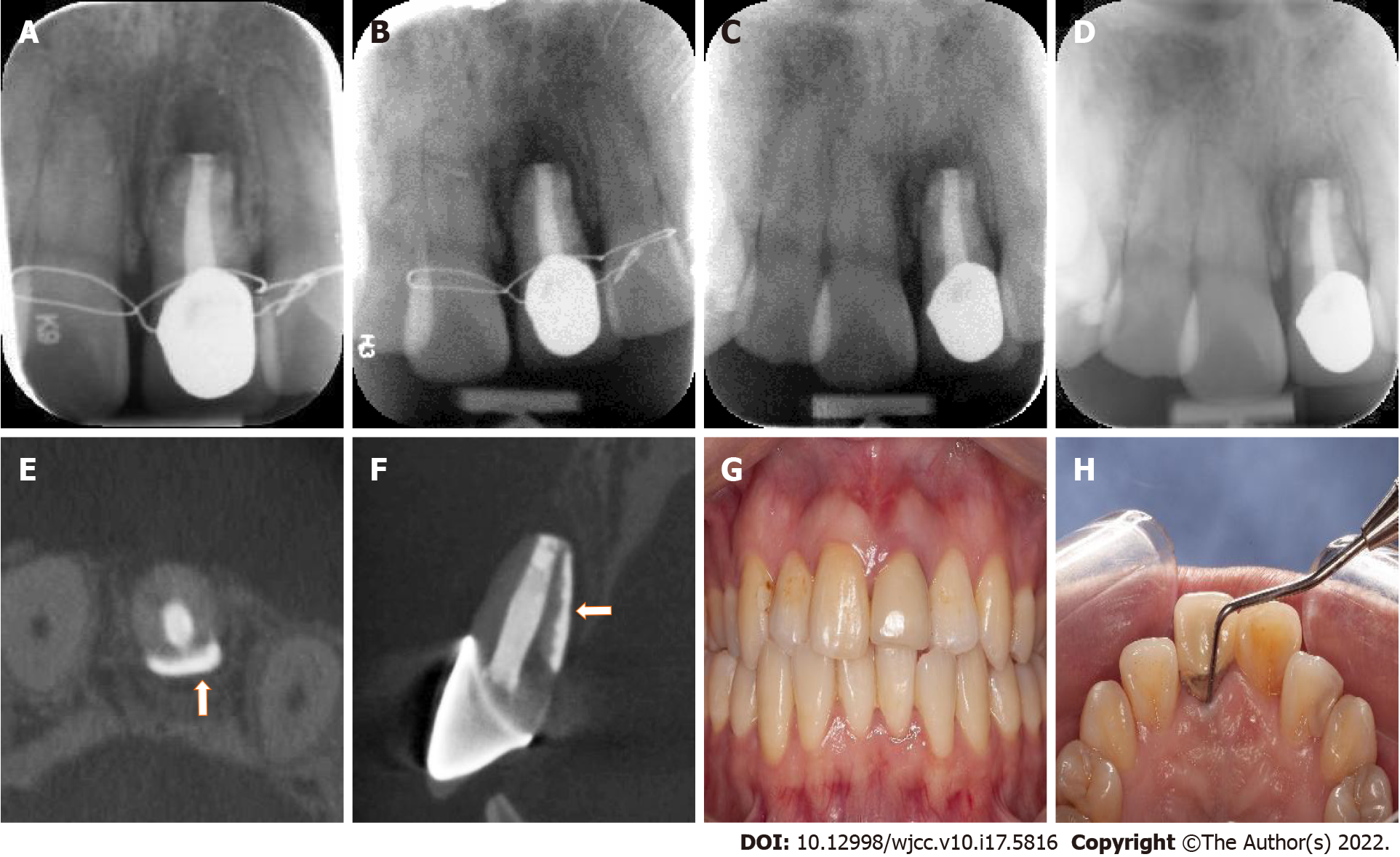
Figure 3 Postoperative images within six months.
A: Immediate postoperative radiograph; B: One-month review radiograph; C: Three-month review radiograph; D: Six-month review radiograph; E and F: Cone beam computed tomography cross-sectional and sagittal-section images at the six-month review showing significant bone and periodontal regeneration (arrowhead) around the root; G: Labial view of tooth #9 at the six-month review; H: Palatal periodontal probing of tooth #9 at the six-month review showing normal periodontal probing depth.
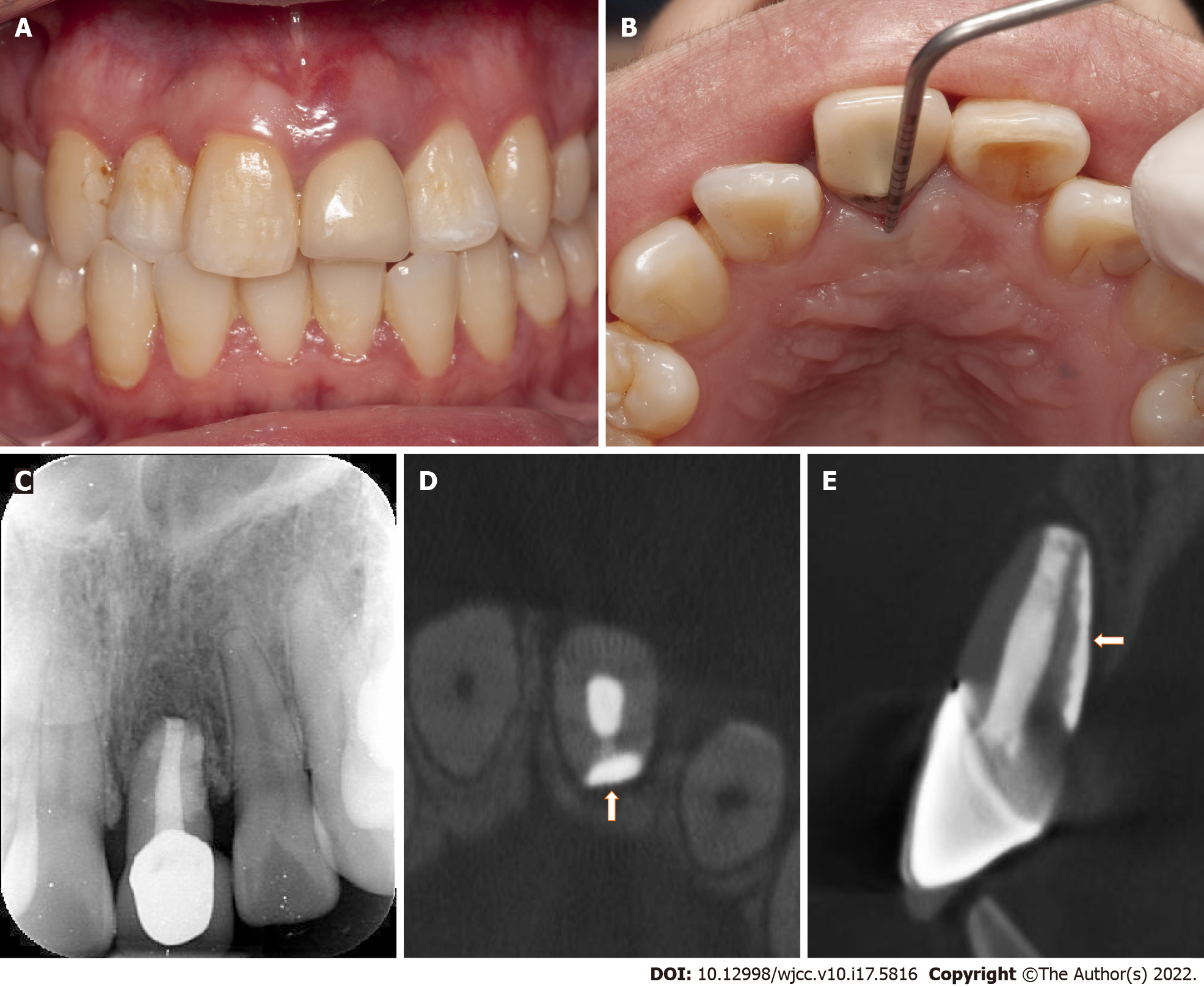
Figure 4 Postoperative images at one-year review.
A: Labial view of tooth #9 at one-year review; B: Palatal periodontal probing of tooth #9 at one-year review showing normal periodontal probing depth; C-E: Radiograph and cone beam computed tomography cross-sectional and sagittal-section images at one-year review showing almost normal bone and periodontal structure (arrowhead) around the root.
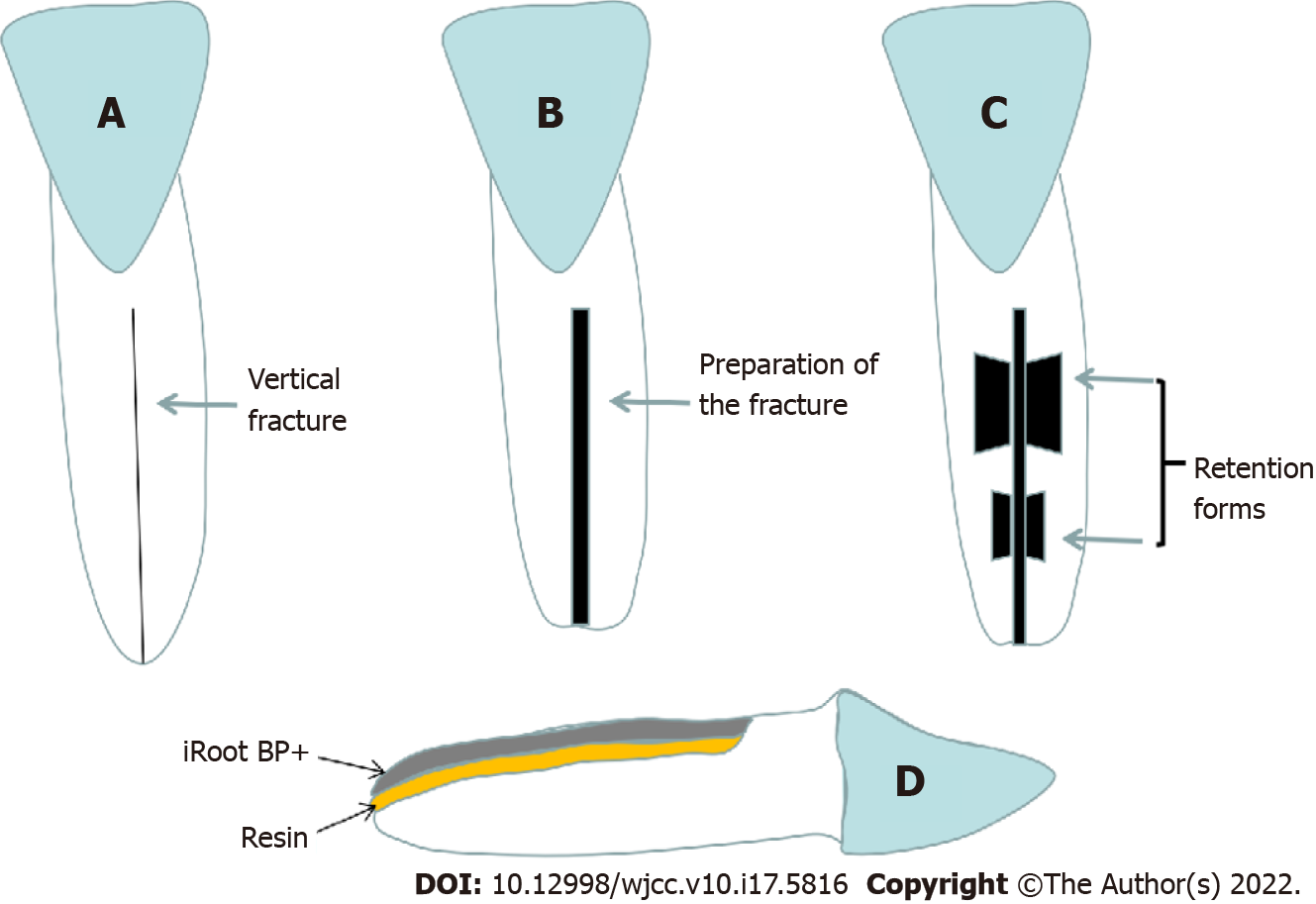
Figure 5 Schematic illustration of the fracture and retention form preparation.
A: Original vertical root fracture line; B: Cleaning and enlargement of the fracture line; C: Preparation of the trapezoidal retention forms along the fracture; D: Side view of the filling of the fracture and retention forms using combination of resin and iRoot BP Plus.
- Citation: Zhong X, Yan P, Fan W. New approach for the treatment of vertical root fracture of teeth: A case report and review of literature. World J Clin Cases 2022; 10(17): 5816-5824
- URL: https://www.wjgnet.com/2307-8960/full/v10/i17/5816.htm
- DOI: https://dx.doi.org/10.12998/wjcc.v10.i17.5816


