©The Author(s) 2025.
World J Orthop. Nov 18, 2025; 16(11): 110093
Published online Nov 18, 2025. doi: 10.5312/wjo.v16.i11.110093
Published online Nov 18, 2025. doi: 10.5312/wjo.v16.i11.110093
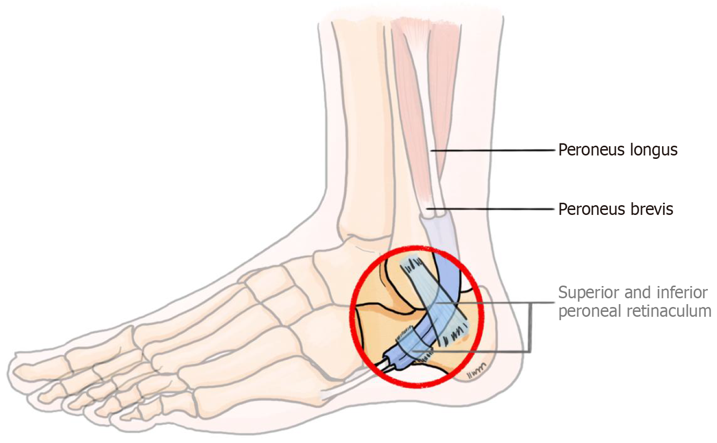
Figure 1 Illustration of structures contributing to lateral ankle snapping: Peroneal tendons beneath the superior and inferior peroneal retinacula.
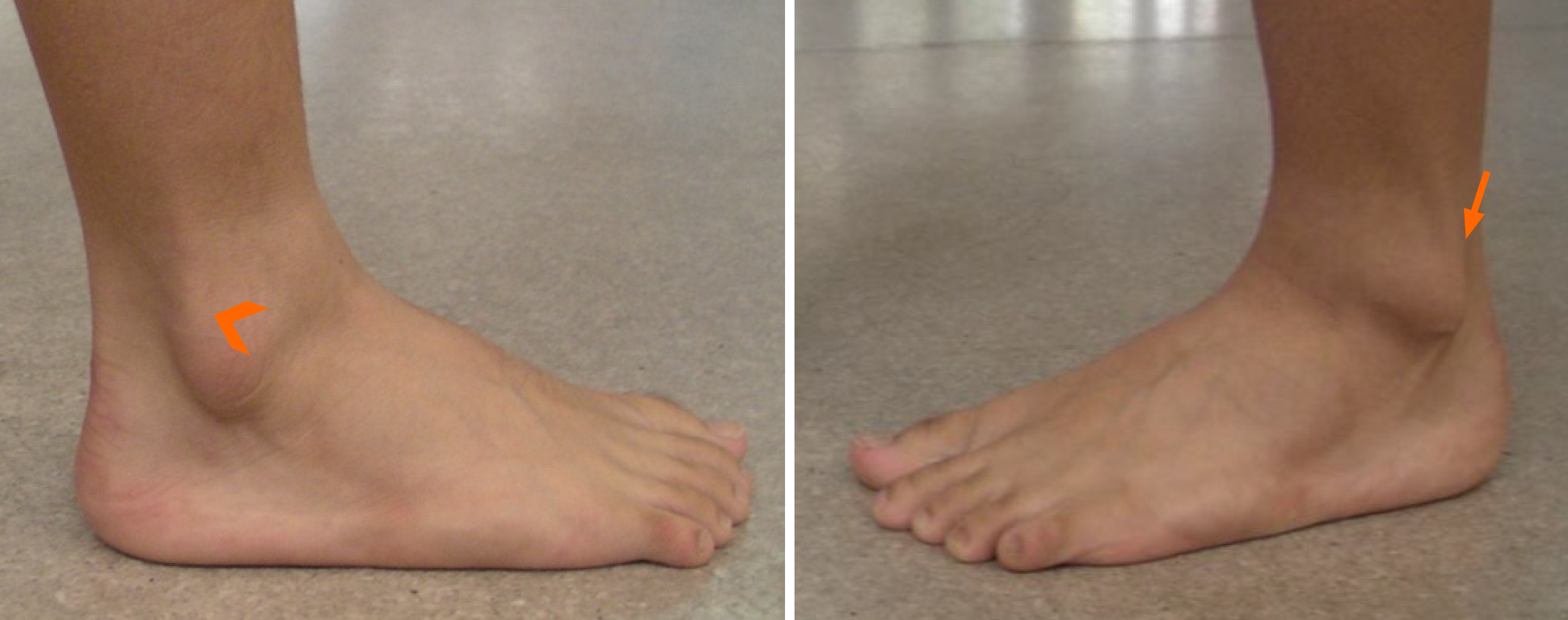
Figure 2 Clinical images of anteriorly dislocated peroneal tendons (arrowhead) and the normal anatomical position of the peroneal tendons posterior to the lateral malleolus (arrow).
Figure 3 Illustration of the Eckert-Davis-Oden grading system for superior peroneal retinaculum injury.
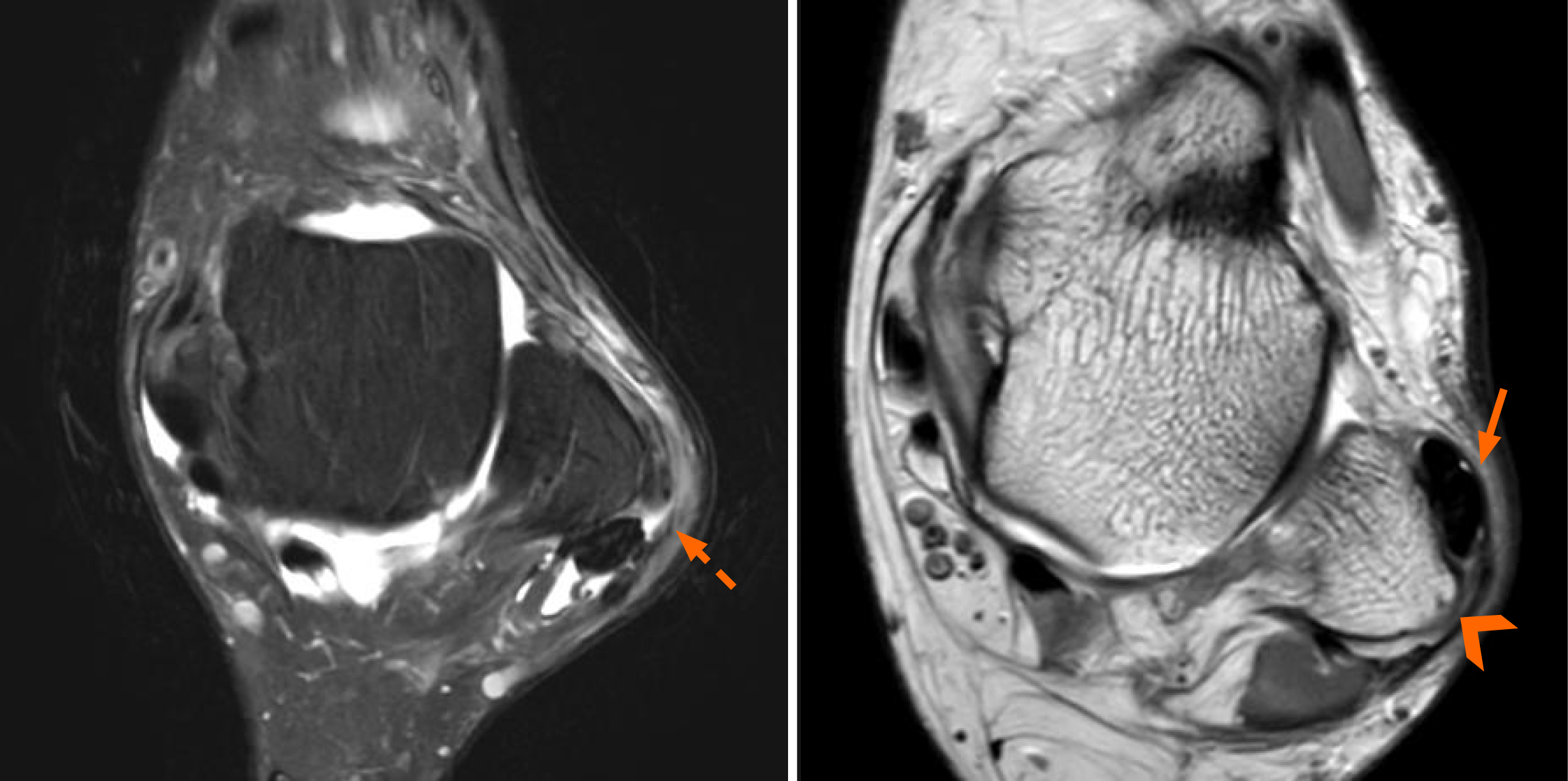
Figure 4 Magnetic resonance imaging shows dislocated peroneal tendons (arrow) and a torn superior peroneal retinaculum (dotted arrow), accompanied by a convex peroneal groove (arrowhead).
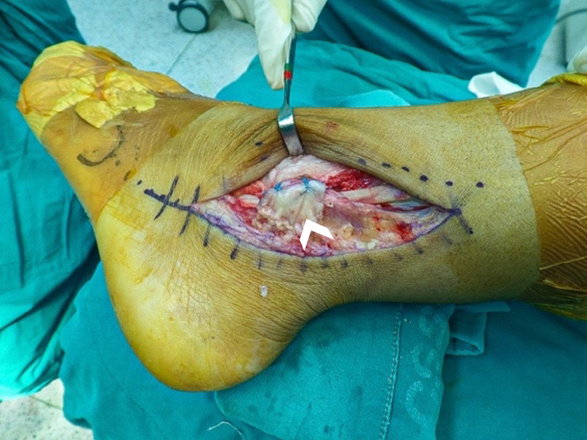
Figure 5 Post-repair intraoperative pictures of the superior peroneal retinaculum (arrowhead).
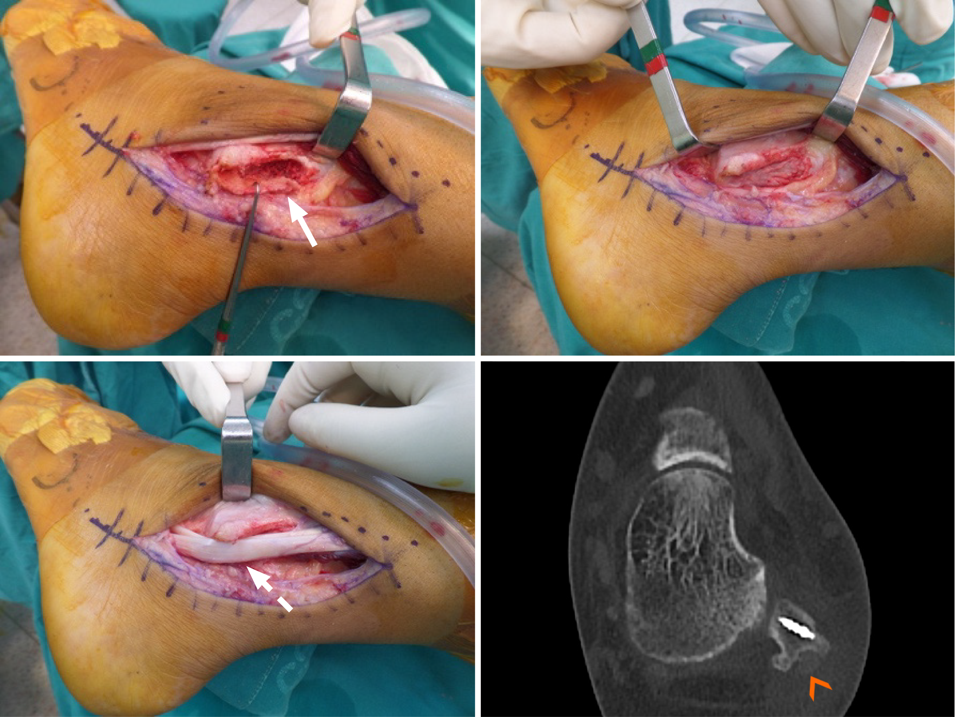
Figure 6 Intraoperative images of a groove deepening procedure: Creating an osteocartilagenous flap (arrow), impacting the underlying cancellous bone to deepen the groove before repositioning the peroneal tendons (dotted arrow).
A postoperative computed tomography image demonstrates the recreated peroneal groove (arrowhead) and superior peroneal retinaculum repair using a suture anchor.
Figure 7 Illustration of distal peroneal tendon instability.
A: The inferior peroneal retinaculum stabilizes peroneal tendons at the level of the peroneal tubercle; B: Tear of the inferior peroneal retinaculum leads to dislocation of the peroneal longus tendon over the peroneal tubercle.
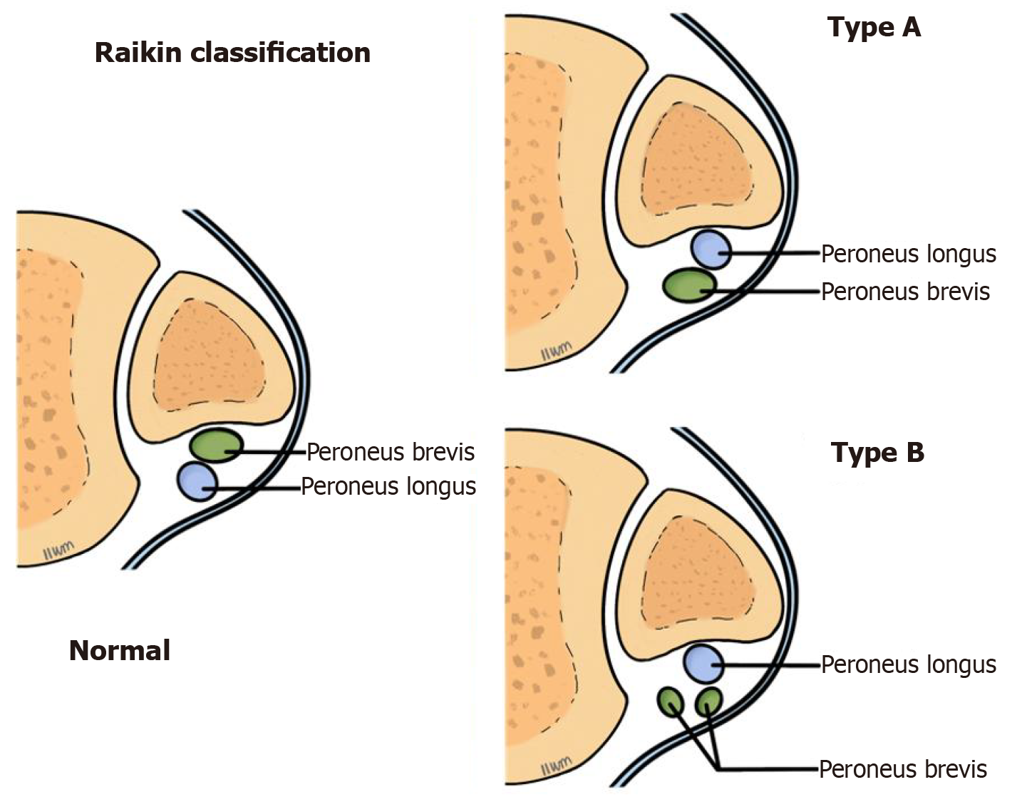
Figure 8 Illustration of the Raikin classification system for intrasheath peroneal subluxation.
Figure 9 Ultrasound images demonstrate the switching positions between the peroneus longus (arrowhead) and the peroneus brevis (arrow) tendons, occurring inside an intact superior peroneal retinaculum.
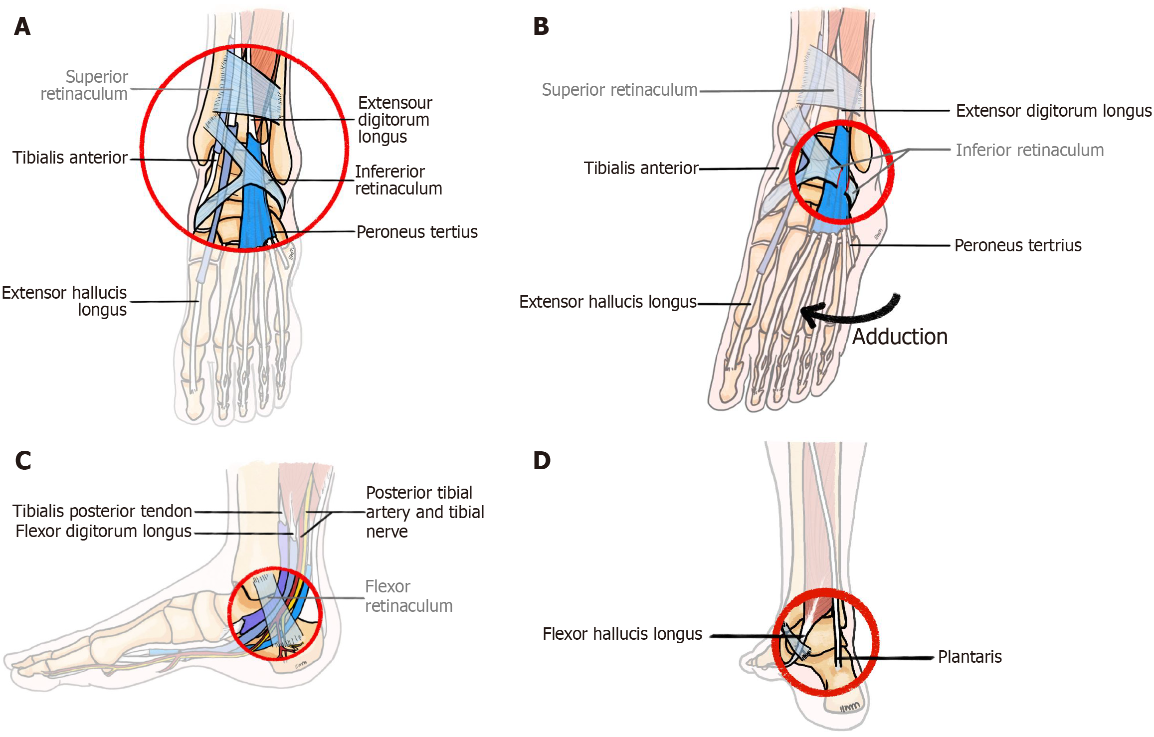
Figure 10 Illustration of the structures contributing to ankle snapping.
A: Illustration of the structures contributing to anterior ankle snapping - the tibialis anterior tendon, extensor digitorum longus tendon, peroneus tertius tendon, along with the talar head, all covered by the inferior extensor retinaculum; B: Illustration of anterolateral snapping due to an insufficient, torn, or scarred inferior extensor retinaculum, resulting in medial dislocation of the extensor digitorum longus tendon during foot adduction; C: Illustration of the structures contributing to medial ankle snapping - the tibialis posterior tendon and flexor digitorum longus traversing the tarsal tunnel, covered by the flexor retinaculum; D: Illustration of the structures contributing to posterior ankle snapping - the flexor hallucis longus and plantaris tendons.
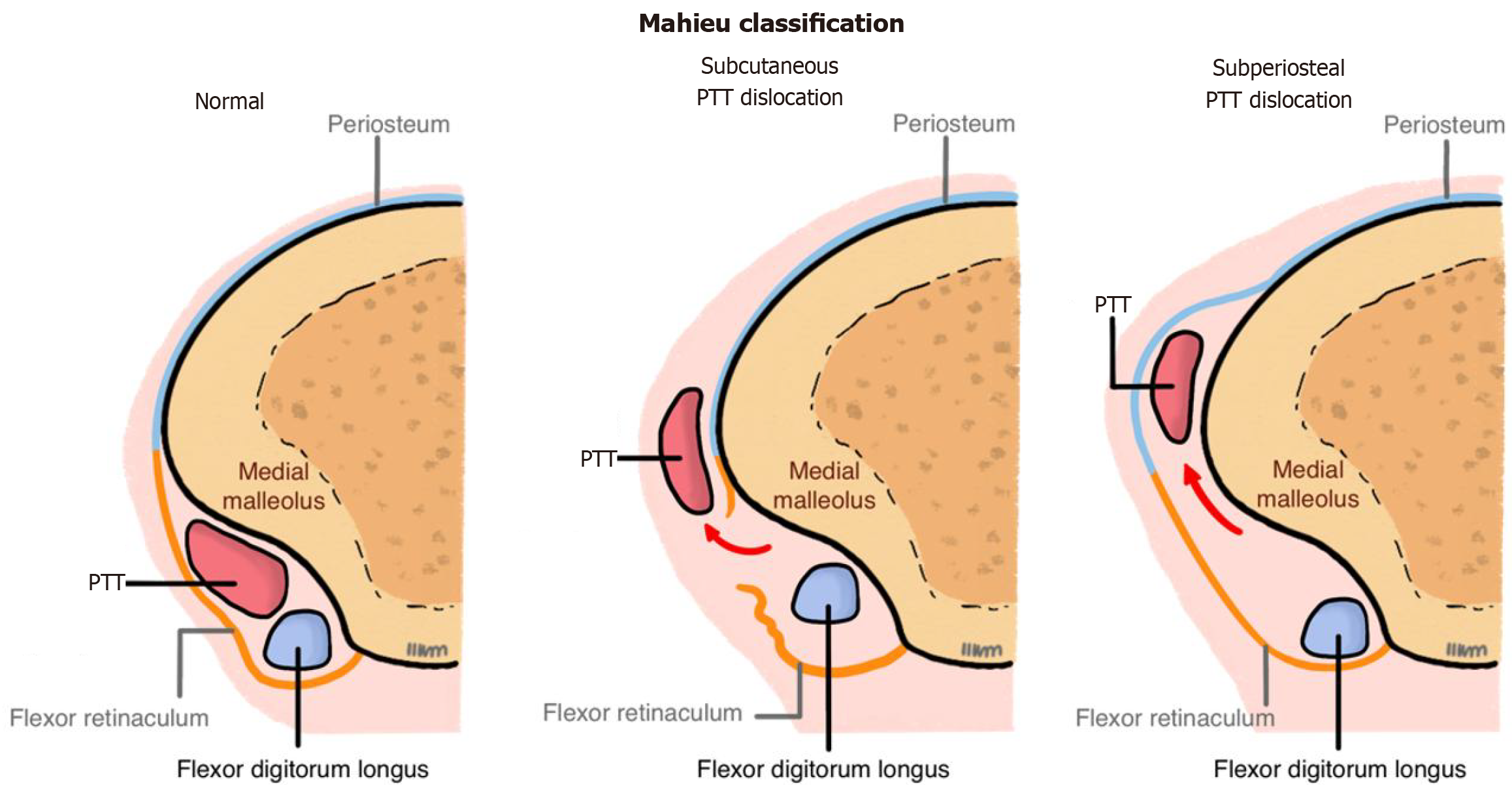
Figure 11 Illustration of the Mahieu classification system for posterior tibial tendon dislocation.
PTT: Posterior tibial tendon.
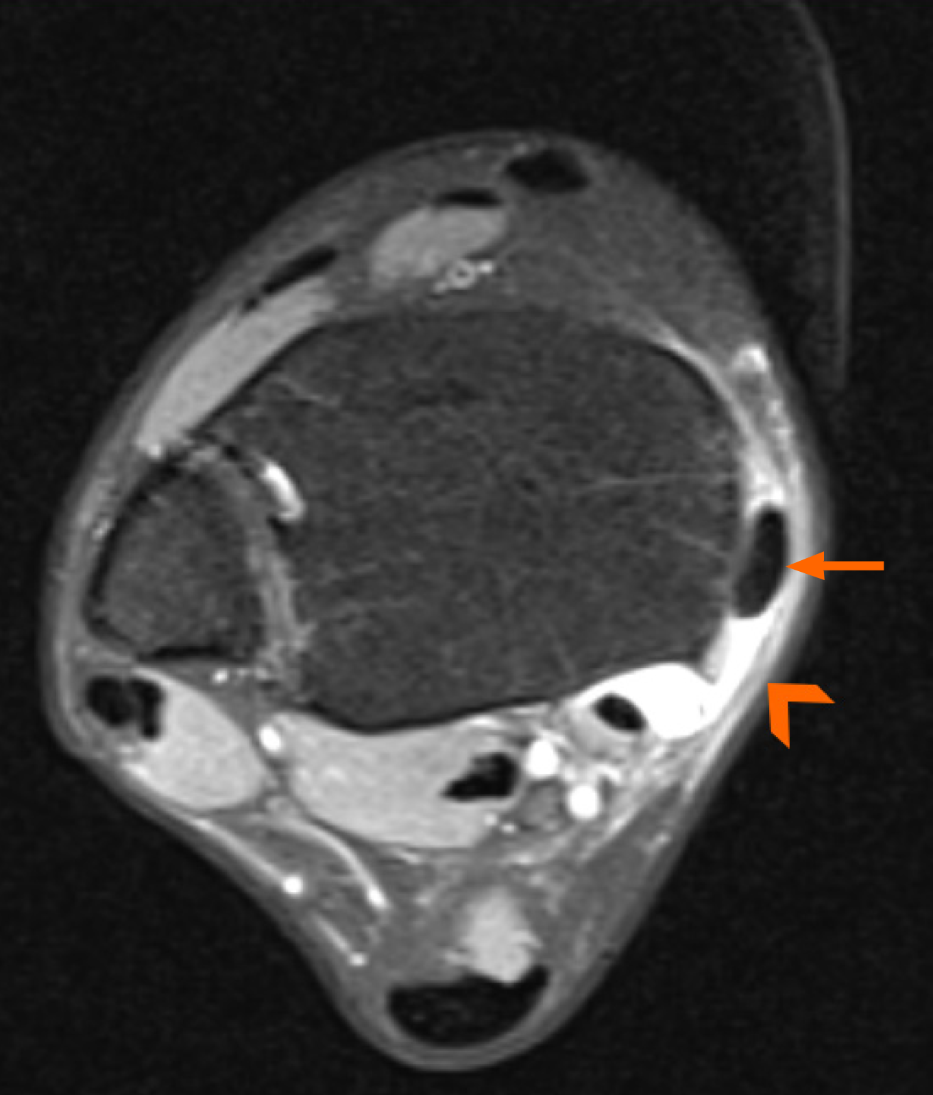
Figure 12 Magnetic resonance imaging of the dislocated posterior tibial tendon (arrow) underneath the redundant flexor retinaculum (arrowhead).
Figure 13 Intraoperative pictures of a pseudoretinaculum with a dislocatable posterior tibial tendon (arrow), and the reduced tendon beneath the repaired flexor retinaculum (arrowhead).
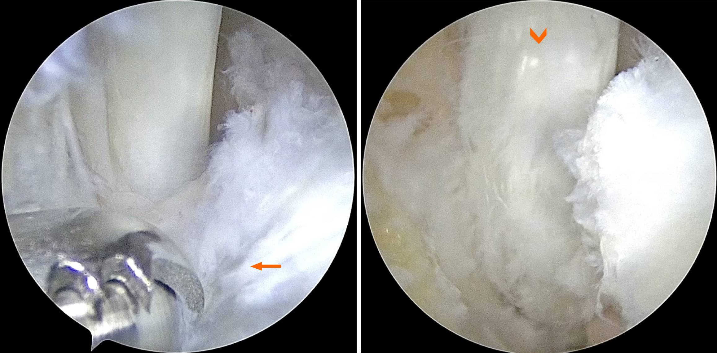
Figure 14 Arthroscopic view showing the release of the flexor hallucis longus tendon pulley (arrow), which exposes the flexor hallucis longus tendon underneath (arrowhead).
- Citation: Riewruja K, Wattanatanagorn T, Apinun J. Snapping phenomenon around the ankle: An anatomy-based review. World J Orthop 2025; 16(11): 110093
- URL: https://www.wjgnet.com/2218-5836/full/v16/i11/110093.htm
- DOI: https://dx.doi.org/10.5312/wjo.v16.i11.110093


