Copyright
©The Author(s) 2025.
World J Gastrointest Surg. Mar 27, 2025; 17(3): 102428
Published online Mar 27, 2025. doi: 10.4240/wjgs.v17.i3.102428
Published online Mar 27, 2025. doi: 10.4240/wjgs.v17.i3.102428
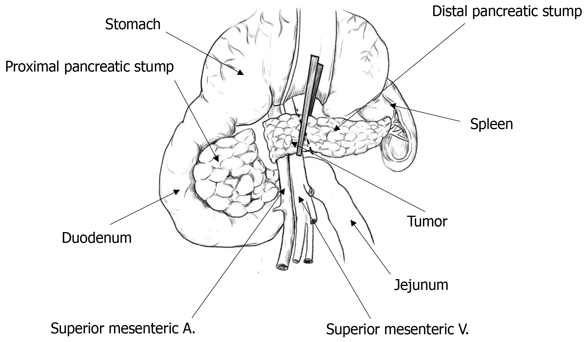
Figure 1 Schematic diagram of pancreatic mass resection.
A: Artery; V: Vein.
Figure 2 Schematic diagram of the interlocking fixation of the drainage tube.
A: A silicone drainage tube tied with suture is placed into the main pancreatic duct. Another suture is inserted through the surface of the pancreas and exited from the section, then go the other way, namely U-shaped stitch; B: Tie the two sutures separately; C: Tightening the knot and cutting off the excess, and complete the interlocking fixation.
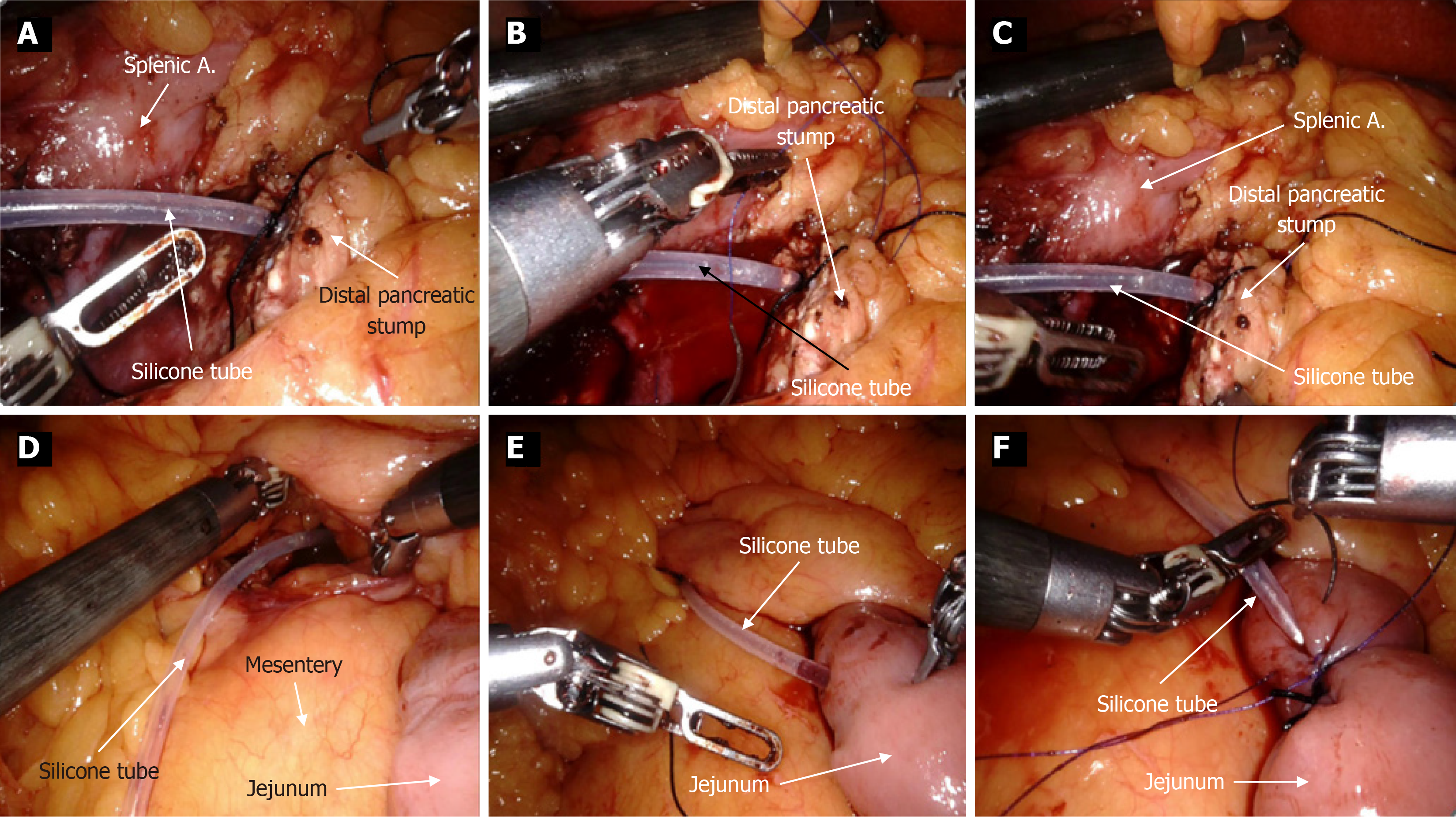
Figure 3 Clinical photographs depicting the step-by-step process of the bridge drainage procedure.
A: Tie a suture around the surface of the drainage tube and then insert it into the main pancreatic duct; B: Use 4-0 polypropylene non-absorbable suture to create a U-shaped stitch; C: Secure the Prolene suture and the tied suture together in an interlocking manner; D: Pass the other side of the drainage tube through the transverse mesocolon; E: Pass through the transverse mesocolon and into the jejunum approximately 10-15 cm below the ligament of Treitz; F: Secure and embed the drainage tube using barbed sutures. A: Artery.
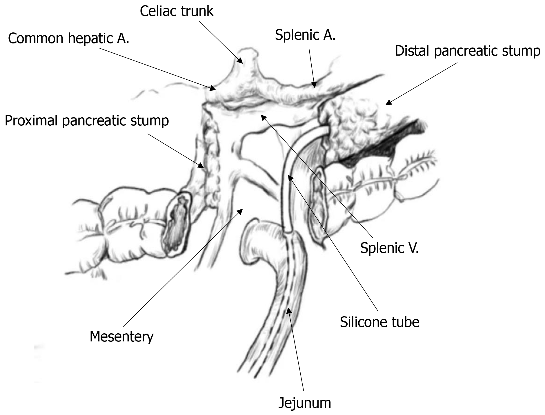
Figure 4 Illustration of the application of interlocking main pancreatic duct-jejunal bridge drainage for middle pancreatectomy.
A: Artery; V: Vein.
Figure 5 Schematic diagram of traditional duct-to-mucosa pancreaticojejunostomy used in mid-pancreatectomy.
A: Artery; V: Vein.
- Citation: Lu XY, Tan XD. Clinical outcomes of interlocking main pancreatic duct-jejunal internal bridge drainage in middle pancreatectomy: A comparative study. World J Gastrointest Surg 2025; 17(3): 102428
- URL: https://www.wjgnet.com/1948-9366/full/v17/i3/102428.htm
- DOI: https://dx.doi.org/10.4240/wjgs.v17.i3.102428


