
















Copyright: ©Author(s) 2026.
World J Gastroenterol. Jul 28, 2026; 32(28): 118067
Published online Jul 28, 2026. doi: 10.3748/wjg.118067
Published online Jul 28, 2026. doi: 10.3748/wjg.118067
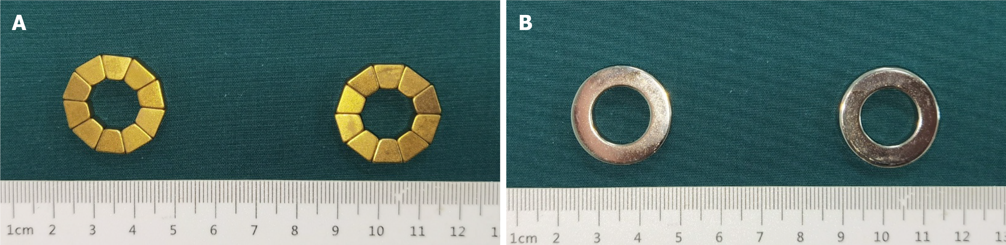
Figure 1 Photographs of the magnets used for gastroenterostomy.
A: Deformable self-assembling magnetic anastomosis ring; B: Conventional magnetic ring.
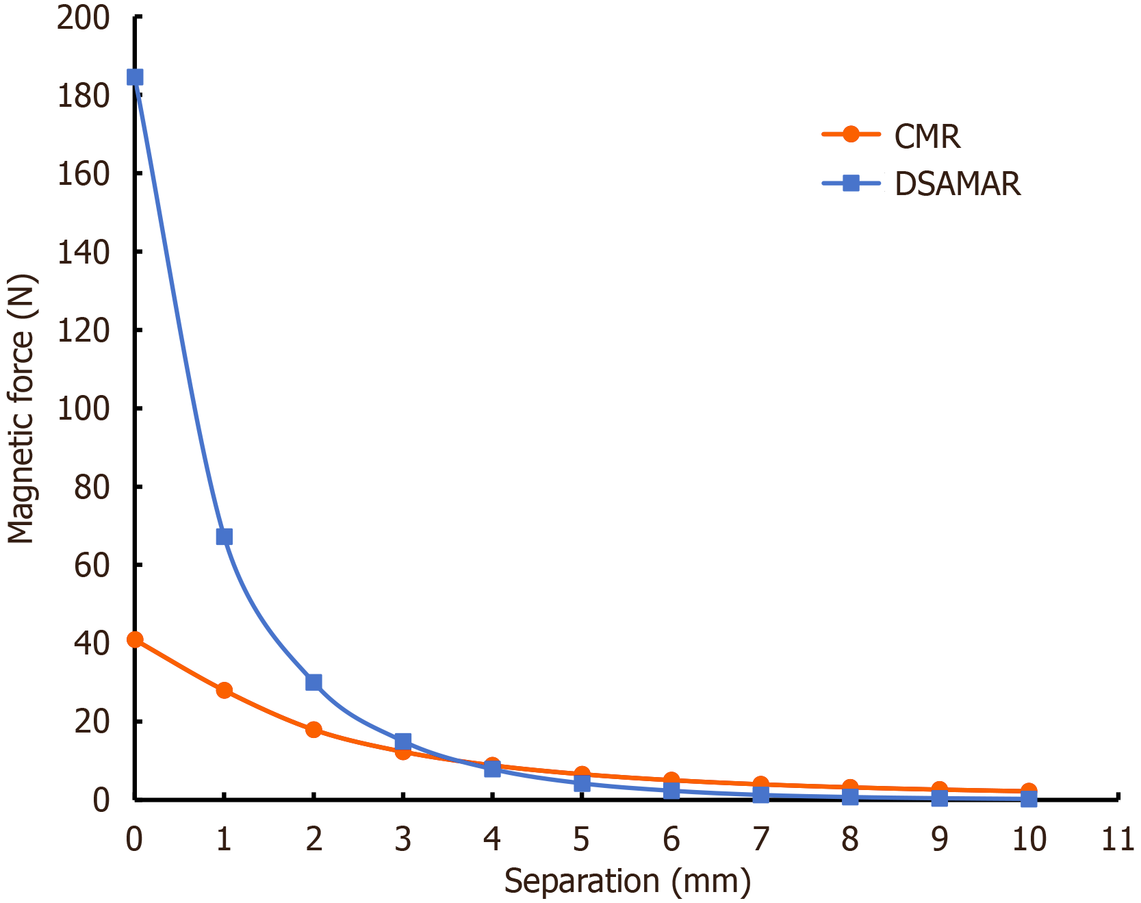
Figure 2 Magnetic force-displacement curves of deformable self-assembling magnetic anastomosis ring and conventional magnetic ring.
DSAMAR: Deformable self-assembling magnetic anastomosis ring; CMR: Conventional magnetic ring.
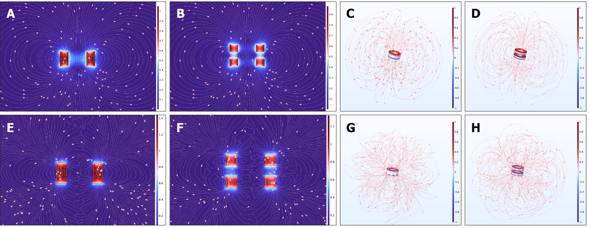
Figure 3 Computer simulation analysis.
A: Magnetic field density distribution of the conventional magnetic ring (CMR) at zero distance; B: Magnetic field density distribution of the CMR at a distance of 5 mm; C: Magnetic field distribution of a CMR; D: Magnetic field distribution when two CMRs attract each other at a distance of 5 mm; E: Magnetic field density distribution of the deformable self-assembling magnetic anastomosis ring (DSAMAR) at zero distance; F: Magnetic field density distribution of the DSAMAR at a distance of 5 mm; G: Magnetic field distribution of the DSAMAR; H: Magnetic field distribution when two DSAMARs attract each other at a distance of 5 mm.
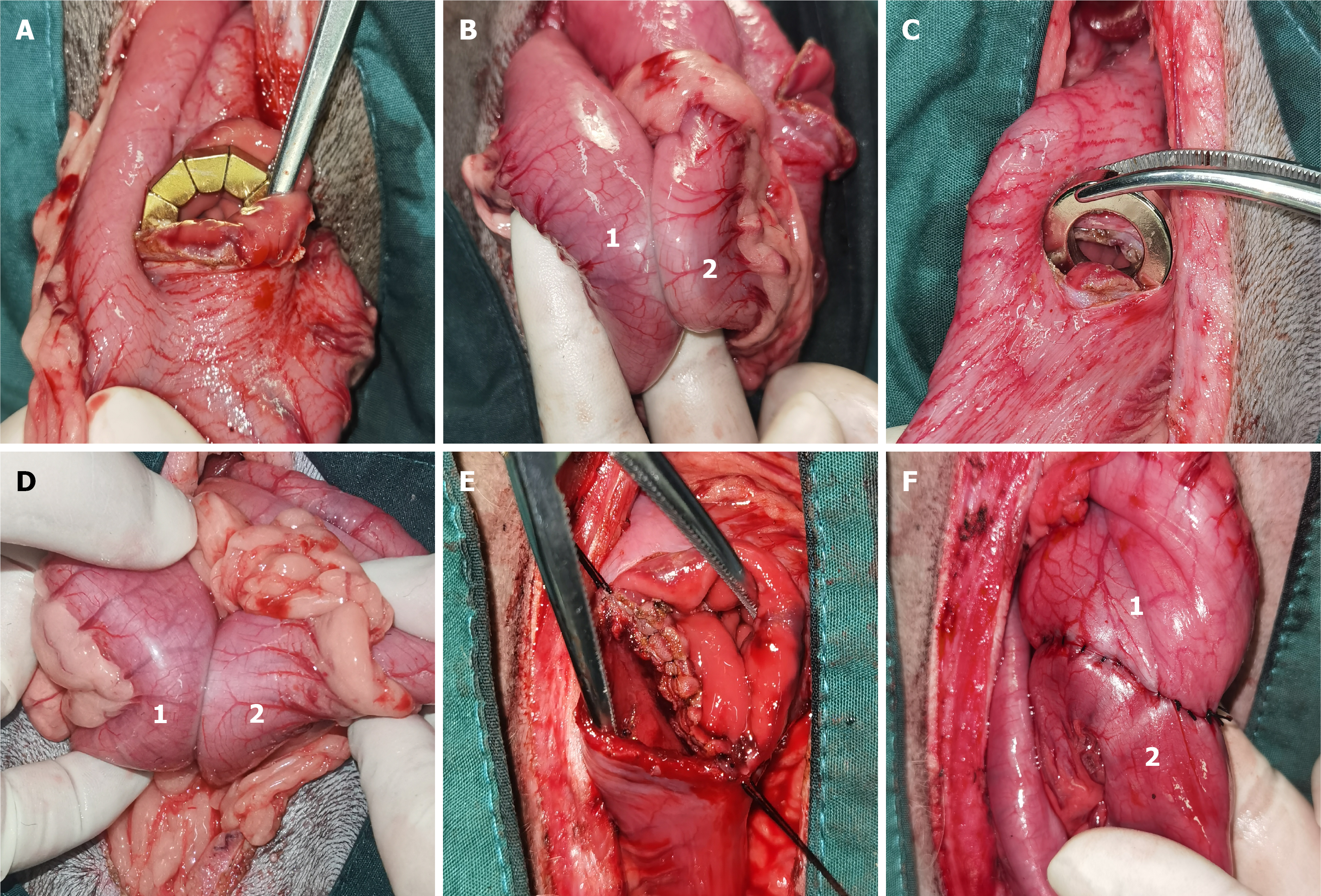
Figure 4 Representative images of intraoperative operations.
A: The deformable self-assembling magnetic anastomosis ring was inserted through an incision in the anterior wall of the stomach; B: The two deformable self-assembling magnetic anastomosis rings on the gastric and duodenal sides attract each other; C: The conventional magnetic ring was inserted through an incision in the anterior wall of the stomach; D: The two conventional magnetic rings on the gastric and duodenal sides attract each other; E and F: Two layers of interrupted sutures were placed for gastroenterostomy suture anastomosis. 1 indicates the stomach, and 2 indicates the duodenum.
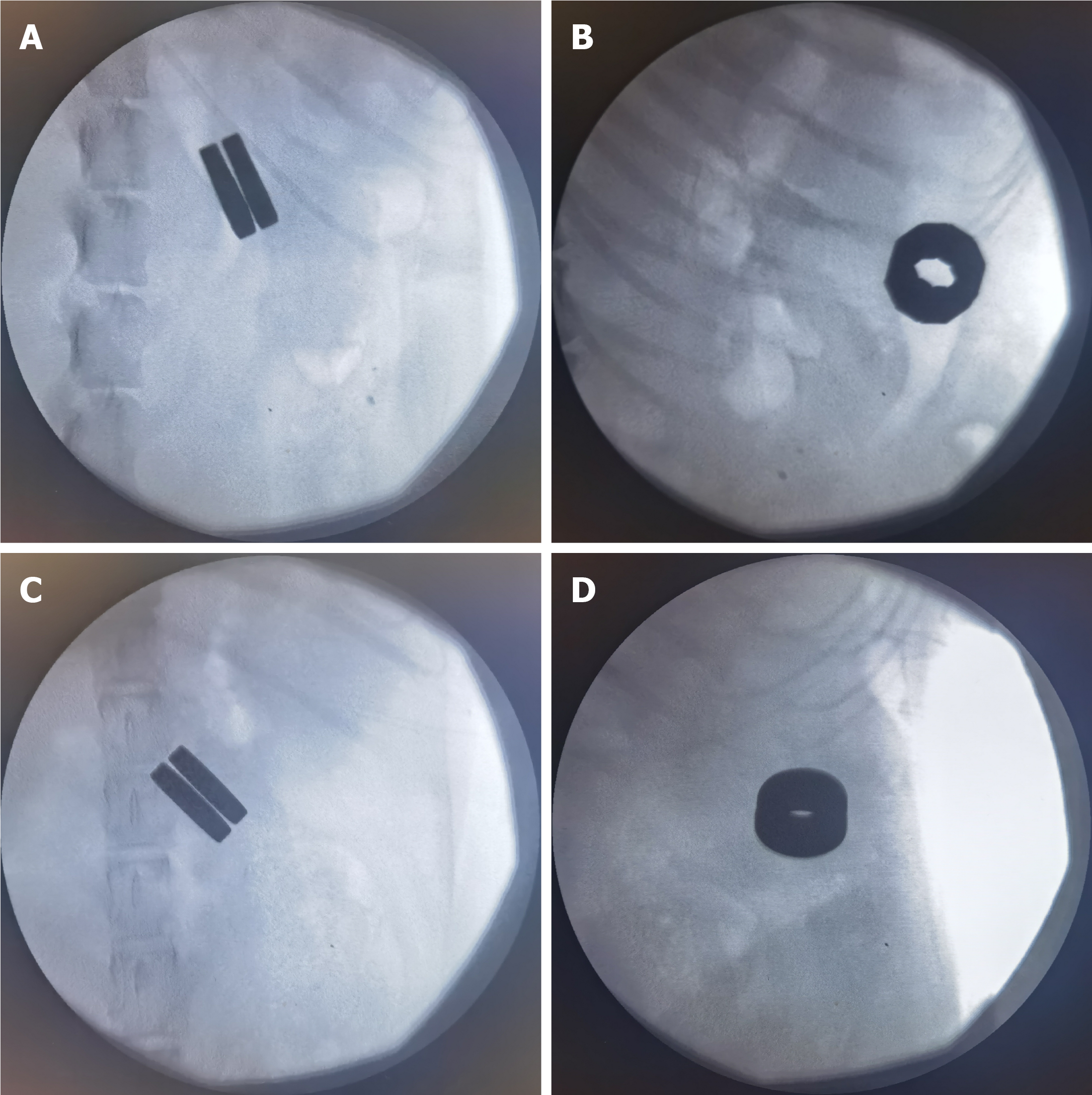
Figure 5 X-ray examination after magnamosis.
A and B: Anteroposterior and lateral radiographs after gastroenterostomy using the deformable self-assembling magnetic anastomosis ring; C and D: Anteroposterior and lateral radiographs after gastroenterostomy using the conventional magnetic ring.
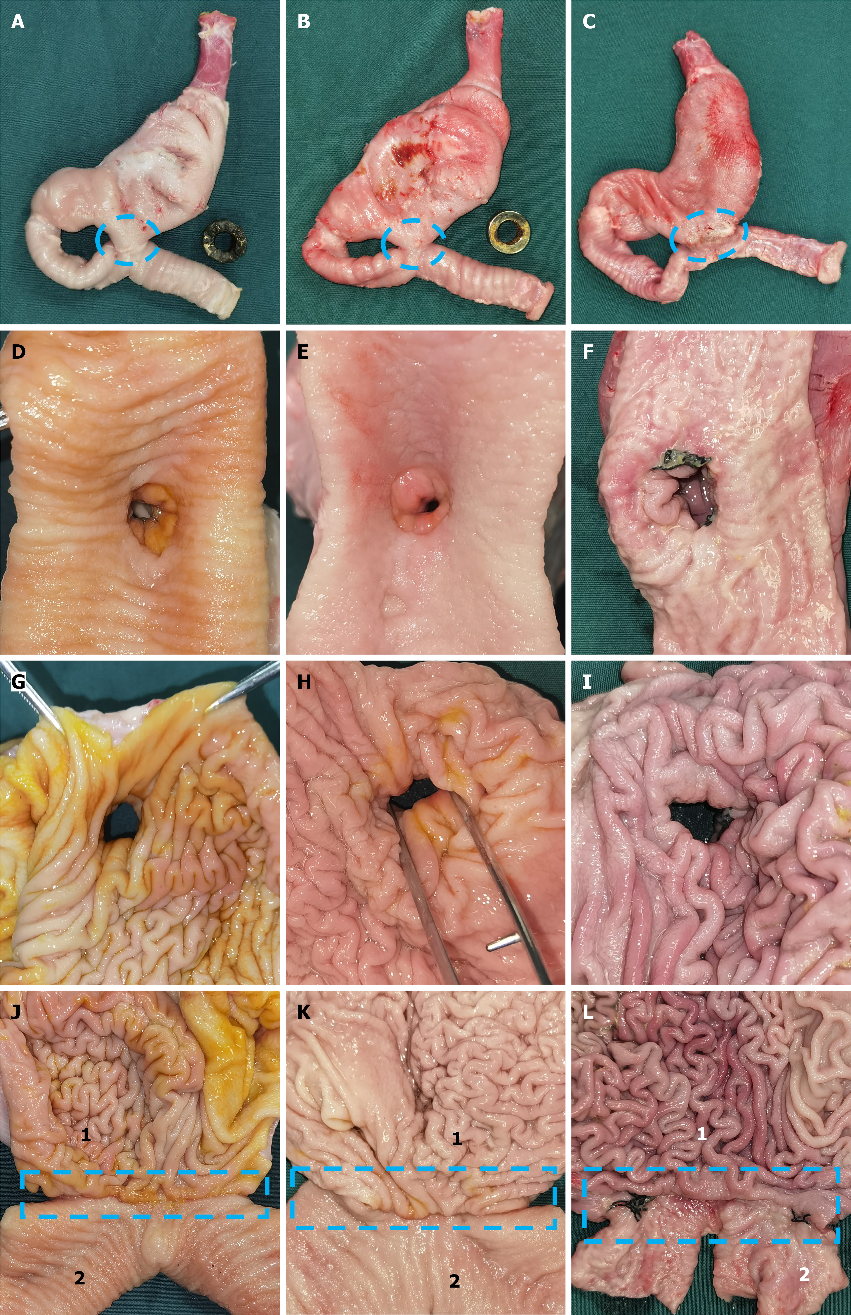
Figure 6 Gross evaluation of anastomosis specimens.
A-C: Images of the serosal surface of the anastomosis: Deformable self-assembling magnetic anastomosis ring (DSAMAR) group (A), conventional magnetic ring (CMR) group (B), and hand-sewn group (C); D-F: Observation of the anastomosis from the duodenal side: DSAMAR group (D), CMR group (E), and hand-sewn group (F); G-I: Observation of the anastomosis from the gastric side: DSAMAR group (G), CMR group (H), and hand-sewn group (I); J-L: Images of the mucosal surface of the anastomosis: DSAMAR group (J), CMR group (K), and hand-sewn group (L). 1 indicates the stomach, and 2 indicates the duodenum.
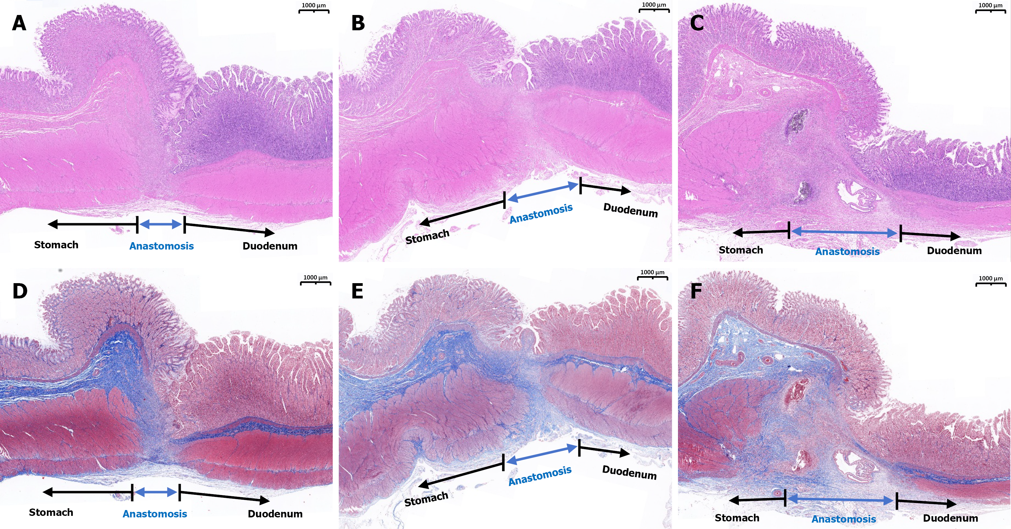
Figure 7 Histological evaluation of anastomosis in each group.
A-C: Hematoxylin and eosin staining (1.5 ×): Deformable self-assembling magnetic anastomosis ring group (A), conventional magnetic ring group (B), and hand-sewn group (C); D-F: Masson’s trichrome staining (1.5 ×): Deformable self-assembling magnetic anastomosis ring group (D), conventional magnetic ring group (E), and hand-sewn group (F).
- Citation: Zhang MM, Xu SQ, Wu HX, Ren HL, Wan JH, Zhong QY, Chen MY, Zhang QF, Gong RM, Yusif-Zada K, Badarch BI, Shi AH, Lyu Y, Liu XM, Yan XP. Comparison of the anastomotic effects of combined-type and whole-type magnetic rings for gastrointestinal anastomosis in beagles. World J Gastroenterol 2026; 32(28): 118067
- URL: https://www.wjgnet.com/1007-9327/full/v32/i28/118067.htm
- DOI: https://dx.doi.org/10.3748/wjg.118067