Published online May 28, 2012. doi: 10.4329/wjr.v4.i5.193
Revised: August 7, 2011
Accepted: August 14, 2011
Published online: May 28, 2012
The interpretation of spinal images fixed with metallic hardware forms an increasing bulk of daily practice in a busy imaging department. Radiologists are required to be familiar with the instrumentation and operative options used in spinal fixation and fusion procedures, especially in his or her institute. This is critical in evaluating the position of implants and potential complications associated with the operative approaches and spinal fixation devices used. Thus, the radiologist can play an important role in patient care and outcome. This review outlines the advantages and disadvantages of commonly used imaging methods and reports on the best yield for each modality and how to overcome the problematic issues associated with the presence of metallic hardware during imaging. Baseline radiographs are essential as they are the baseline point for evaluation of future studies should patients develop symptoms suggesting possible complications. They may justify further imaging workup with computed tomography, magnetic resonance and/or nuclear medicine studies as the evaluation of a patient with a spinal implant involves a multi-modality approach. This review describes imaging features of potential complications associated with spinal fusion surgery as well as the instrumentation used. This basic knowledge aims to help radiologists approach everyday practice in clinical imaging.
- Citation: Nouh MR. Spinal fusion-hardware construct: Basic concepts and imaging review. World J Radiol 2012; 4(5): 193-207
- URL: https://www.wjgnet.com/1949-8470/full/v4/i5/193.htm
- DOI: https://dx.doi.org/10.4329/wjr.v4.i5.193
Successful spinal fusion procedures appeared in the medical literature in the early 20th century[1,2]. The development of an integrated osseous fusion complex is essential for the long-term success of these procedures[3]. Early surgeries relied upon extended bracing for solid fusion to occur with considerably long convalescence periods[3]. Currently, a vast array of implants and surgical approaches are available for spinal surgeries to aid graft incorporation with early mobility and shorten postoperative recovery period[3-9]. The choice of fixation device and technique depends on the clinical problem, the anatomic location, and the surgeon’s preference[3-9].
The goal of spinal instrumentation is to maintain or correct anatomic alignment of spinal segments by sharing the loads acting on the spine, usually until solid biological fusion occurs[5-9]. Subsequent instrument failure occurs if solid bony fusion is not achieved[5-9].
Radiologists are required to be familiar with the spinal instrumentation in common use as well as those used in his/her region to promote communication with the referring physician and awareness of potential complications of such procedures. This review will highlight these procedures and the common techniques, surgical approaches, postoperative imaging features as well as common complications associated with them.
The spine is a complex structure that transmits loads from the upper body through the pelvis into the lower extremities[3,7]. A spinal motion segment is the smallest functional unit addressing spinal biomechanics. It consists of two adjacent vertebrae, an intervertebral disc, various ligaments and apophyseal joints. Harmonic interaction of these elements as well as surrounding spinal musculature results in spinal motion segment stability during the applied forces of daily activities[10].
Accordingly, the American Academy of Orthopedic Surgeons has basically defined spinal instability as an abnormal response to applied loads, characterized by movement in the motion segment beyond normal constraints[11].
Denis’s spinal model (Table 1) is widely employed by spinal surgeons to address genuine native gross spinal stability[12].
| Spinal column | Components | Primary function | Secondary function |
| Anterior | ALL, anterior 2/3 of the vertebral body and annulus fibrosus | Bears axial load | Resist extension |
| Middle | Posterior 2/3 of the vertebral body and annulus fibrosus, nucleus bulbosus and PLL | Resist flexion | Shares in axial loading |
| Posterior | Posterior vertebral arch elements | Spinal stability during rotational movements | Resist flexion |
In general, two of the three spinal columns must be anatomically intact for functional stability. Violation of more than one column by trauma, infection, tumor, degenerative change, or surgical approach will necessitate spinal instrumentation[3].
Listing different spinal instrumentation devices and surgical procedures is beyond the scope of this review. However, a general overview will be provided here.
Spinal instrumentation is commonly performed when spinal stability restoration, deformity correction, spinal-motion segment height restoration and pain relief are desired as in the management of scoliosis and other spinal deformities, spinal degenerative disease, trauma, instability, infection, and neoplasm[13-16]. A combination of both biologic (bone graft) and prosthetic (instruments) materials are usually used to form a construct that aims to maintain spinal stability in an unstable region of the spine[17].
Posterior spinal column reconstruction has been performed for decades using different combinations of plates or rods with hook/wire/pedicle screw systems to form posterior spinal construct devices for different spinal levels[3,5,7].
A posterior approach is usually used when posterior decompression is required in addition to fusion as in degenerative spinal disease. It is more common in dorsal and lumbar regions (e.g., posterior inter-lumbar body fusion or PILF) as it is easier and adequately visualizes neural elements. It avoids the high-risk of the anterior approach in these regions, while it is mostly avoided in the cervical region for cord manipulation risks at that level[3,4].
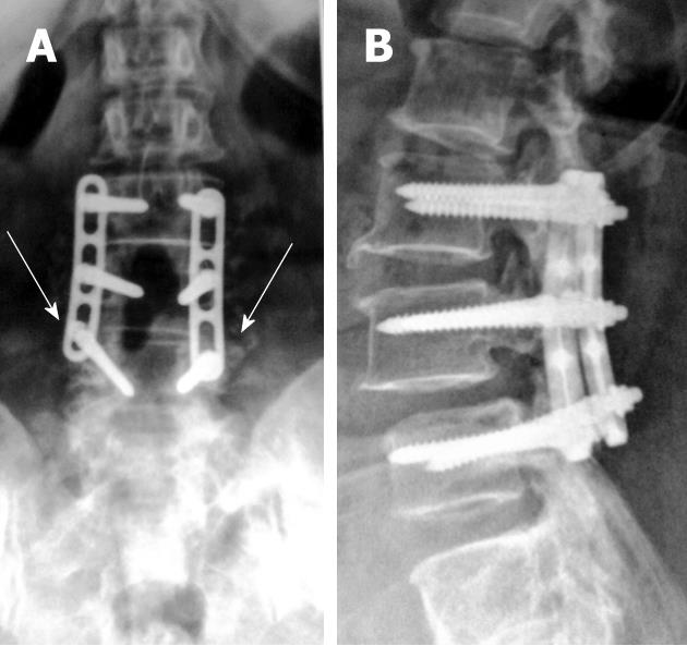
Posterior fusion uses autografts placed along decorticated facets, laminae and/or transverse processes[7]. In PLIF, bilateral partial laminectomies are performed and are followed by diskectomy (Figure 1). Bone graft material is packed into the anterior disk space before the insertion of one or two interbody spacers; placed side by side; and packed with graft material[4,7,8,18].
When there is a severe loss of disk space height and when the insertion of a posterior interbody spacer might cause neurologic compromise, Trans-laminar inter-body fusion with cortical screws is used as a simple method of posterior fixation. The bone graft material is placed laterally (between transverse processes) rather than anteriorly (between vertebral bodies), for posterolateral spinal fusion[4,7,8,18].
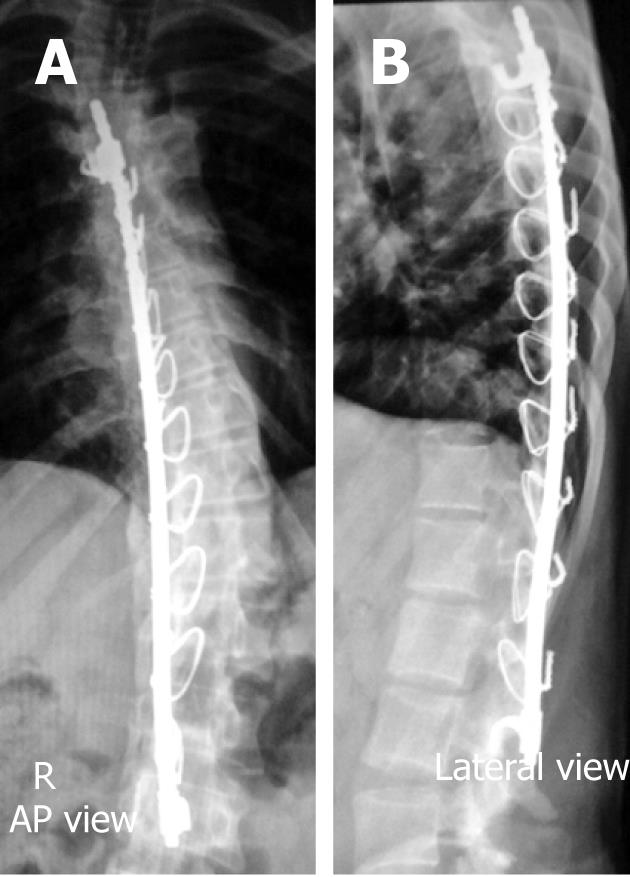
Rods are commonly used for long segment spinal fixations e.g., in scoliosis, as they can be individually cut and molded as required to facilitate maintenance of sagittal alignment, while plates are favored for short segment fixations e.g., in traumatic and degenerative etiologies[4,6,7,18].
Anterior fusion procedures are indicated for discogenic pain where removal of degenerative disk material and replacement for disk height is performed along with anterior osseous fusion for immediate stability. The presence of facet joint disease contra-indicates these procedures[4,7].
Anterior instrumentation may use either rod-screw or plate-screw systems to form a spinal construct. The anterior approach is generally preferred in the cervical spine (commonly known as anterior cervical diskectomy and fusion or ACDF) because of the risk of cord manipulation associated with a posterior approach at this level. Also, implants used posteriorly in the thoracic and lumbar regions are too large imparting greater traction forces that are not needed in the smaller cervical spine[4,7].
On the contrary, in the thoracic and lumbar levels (commonly known as anterior inter-lumbar body fusion or AILF) it is less indicated owing to significant morbidity, as the procedure involves going through the chest and abdominal cavities, and delayed recovery is associated with this approach[4,7].
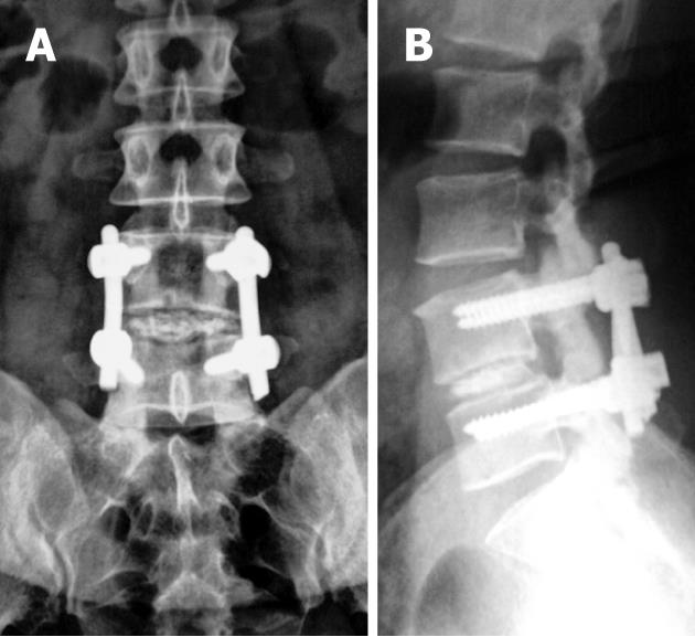
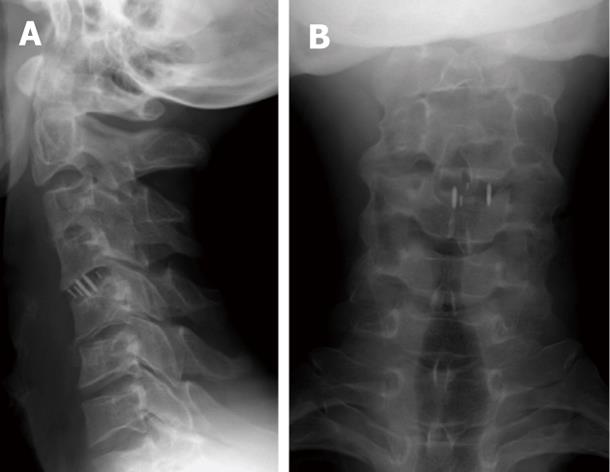
These are a group of materials that have compressive strength and aim mainly to preserve disc space and/or spinal motion heights in diverse indications such as degenerative disc disease, neoplastic disorder, etc. They can be biologic substances like iliac bone grafts (Figure 2) and fibular grafts in cervical regions. Femoral grafts can be used where more spinal axial loads are present as in the lumbar region. Synthetic materials such as stainless, titanium and carbon polymers can be used in threaded and solid forms (Figure 3).
In either situation, the central cavity is typically packed with autologous bone chips, demineralized bone matrix, and/or bone morphogenetic protein to establish bony fusion. The most recent non-metallic synthetic spacers contain two radiopaque markers to enable radiographic assessment of the spacer position (Figure 4)[7,19].
Spinal diseases of neoplastic, infective or traumatic processes may necessitate resection of one or more vertebral bodies under certain circumstances, known as corpectomy or vertebral body replacement. Maintaining the lost spinal segment height is mandatory to preserve functionality and avoid further neural related complications[4].
For corpectomy procedures large strut grafts are used. Femoral strut allografts are designed for use in the lumbar or thoracic spine, while fibular strut allografts or tricortical iliac crest grafts may be used in anterior cervical corpectomy. In all cases, spinal hardware fixations are added to share load-bearing and aid bony fusions[7].
Total disk replacement, also known as disk arthroplasty, is performed in patients where their pain is believed to be discogenic in origin with no nerve root involvement as well as absent spinal stenosis or spondylolisthesis[4,7,20].
These procedures were resorted to in an attempt to avoid the effects on adjacent motion segments and the facets following spinal arthrodesis[21,22].
At least 4 mm of residual disk height and a lack of significant endplate degeneration to provide satisfactory anchorage for the replacement device are pre-requisites. The presence of spinal instability, facet joint degeneration, osteoporosis and/or infection contraindicates total disk replacement[4,23].
The first human disk prosthesis, which consisted of a single ball bearing, was inserted in the late 1950s[24]. Bao et al[25] classified these devices into four categories: (1) low-friction sliding surface; (2) spring-and-hinge systems; (3) contained fluid-filled chambers; and (4) discs comprised of rubber or other elastomers.
The materials used by different manufacturers vary considerably, with many different combinations of metals and polymers.
Yang et al[26], showed good clinical outcome, restored cervical spine mobility and prevented accelerated adjacent cervical segments degeneration at 24-mo follow-up. Yajun et al[27], reported equivocal results for the treatment of lumbar degenerative disc disease compared with fusion after a 2-5-year follow-up period. Their long-term evaluation is still ongoing in the literature.
Spinal fusion procedures reduced pain clinically, but the increased stress on the adjacent segments was a new cause of instability and pain[28-30]. Dynamic stabilization may be an alternative to fusion in some patients with low back pain originating from chronic degeneration of the lumbar spine[31].
The concept of dynamic stabilization relies upon altering load bearing and controlling abnormal motion. This limits the stress placed on the segment adjacent to the level of fusion and thus helps prevent progressive degeneration[31-35].
A wide variety of dynamic stabilization devices is available. These devices may be broadly grouped, according to their design, into the following categories: (1) pedicle screws and artificial ligaments; (2) inter-spinous process decompression devices; and (3) posterior element replacement systems[4].
Radiography is the mainstay used for the postoperative imaging of spinal fusion thanks to its wide availability, cost-effectiveness, and non-invasive nature, although computed tomography (CT) is reported to be a more accurate modality[6,36,37].
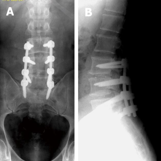
Baseline radiographs or CR images are essential for evaluating spinal construct position (Figure 5) and serve as a starting point for evaluation of future studies, should patients develop symptoms suggesting potential complications. A change in position or instrument failure is often easily appreciated on serial radiographs or CR images[6,37]. Antero-posterior (AP), lateral, oblique, and motion studies (flexion, extension, or lateral bending) images are usually adequate and varies from one institution to another.
In some instances, fluoroscopically positioned images may be needed to judge better alignment of the hardware or osseous structures to identify subtle changes more optimally[9,38,39].
However, the projectional nature of radiography, insensitivity to detect metastasis and to explain neurologic symptoms are drawbacks limiting its yield[4-7].
Polytomography had been used to detect subtle motion at the fusion site[40]. Nowadays, its use is only justified when older stainless steel hardware is present that precludes adequate CT imaging[7,40].
Ultrasound is not commonly used for evaluating potential spinal complications, although detection of superficial abscesses or fluid collections can be accomplished with this technique and may help to guide their aspiration[4,6].
For many years, significant beam hardening and susceptibility artifacts seen on CT and magnetic resonance (MR), respectively, made these imaging tools a poor choice for evaluating patients with spinal metallic implants[41-43]. Patient movement often exacerbates such artifacts, however, this can be overcome with currently available high-speed multidetector CT.
However, with recent advances in CT technology; especially in the multi-detector era; as well as hardware material improvements; including materials with fewer significant artifacts such as titanium, polyethylenes and fibrocarbons; many artificial implants can be imaged with fewer artifacts preserving relevant imaging information[6,7,41,44].
CT is the modality of choice for imaging bony detail in the spine, for accurate assessment of component position, particularly for positioning of pedicle screws, evaluating both spinal and construct alignment, and degree of osseous fusion[6,7,45,46]. It can also evaluate the spinal canal, and potential post-operative complications[6,7,45,46].
Metal-induced artifacts on CT are the results of both hardware-related factors such as hardware composition, geometry (shape), as well as location and imaging technical factors including tube current (in milli-ampere-seconds, mAs); X-ray kilovolt peak (KVp); pitch; and image reconstruction algorithm (filter)[47,48].
Hardware-related factors are beyond the control of the imager. Orthopedic hardware composed of lower X-ray beam attenuation coefficients (density) materials results in fewer artifacts e.g., titanium alloys produce fewer artifacts than stainless steel alloys[47-50].
Thin body parts and thinner parts of the metallic hardware attenuate X-ray beams less than their thicker counterparts producing fewer image-degrading artifacts[47-50]. This could be of clinical application in imaging of the reconstructed cervical spine with downward traction of the shoulders while raising the arms above the head for imaging of the reconstructed dorsal and lumbar spinal regions[47-50].
On the other hand, control of the following imaging factors can significantly improve the resultant hardware images and allows accurate answering of relevant clinical questions.
Most current CT- X-ray tubes operate at 120 kilovolt peak (KVp) as a default setting. This may suffice for imaging cervical spinal hardware in thin patients. However, in chubbier patients and thicker parts such as the dorsal, lumbar and sacral spines, a higher KVp, e.g., 140 KVp can increase the ability of the X-ray beam to penetrate metal[47,51,52].
X-ray tube current: An appropriate increase in tube current setting using the tube’s larger focal spot increases the ability of the X-ray beam to penetrate metal[48-52].
Pitch: The term pitch equals table translation (in millimeters) per gantry rotation divided by beam collimation[53,54]. As the number of detector rows increases the pitch decreases and this reduces metal artifacts[53,54]. Thanks to lower pitch settings of multi-channel CT technologies, the collection of enormous data sets can be achieved. Thus, high-resolution images in axial, sagittal and coronal planes can be obtained[53,54]. Furthermore, excellent post-processing images as volume rendered (VR) and shaded-surface display (SSD) images can be reproduced[48,53,54].
The use of a standard or smooth reconstruction filter is preferred, particularly in the presence of dense metallic hardware and in patients with a large body habitus. The use of wide window settings (3000-4000 HU window width, 800 window levels) facilitates visualization of structures adjacent to metal hardware and reduces the effects of metal artifacts. Gathering the small thickness slices into more thickly reformates helps to reduce metal-induced artifacts and improve signal-to-noise ratio[47,48,50,52].
Volumetric rendering techniques such as VR and SSD impress semitransparent views of bones that tend to reduce metal artifacts allowing proper assessment of metal hardware-bone relationship[47,48,50,52].
CT and plain films virtually provide all relevant diagnostic information on grafts, implants, and hardware, thus magnetic resonance imaging (MRI) was commonly reserved due to magnetic-susceptibility artifacts seen with the old stainless steel alloys[6,7,55].
However, both recent MRI advances and newer magnetically inert polymers used for the manufacture of spinal hardware elements allowed higher resolution images of clinical diagnostic value. MRI has become an integral part of evaluating the patient with painful hardware implants, where clinical findings are non-focal, and laboratory diagnosis is negative for infection[50,55-58].
MRI is sensitive for detecting fractures, pseudo-arthrosis, and infections. It depicts cancellous bone marrow well compared to cortical bone[37].
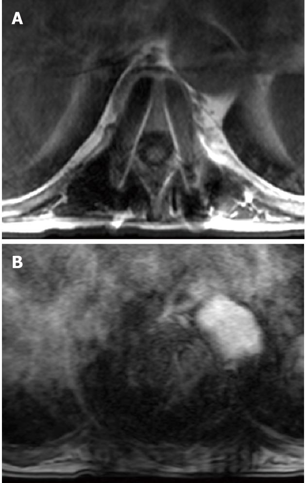
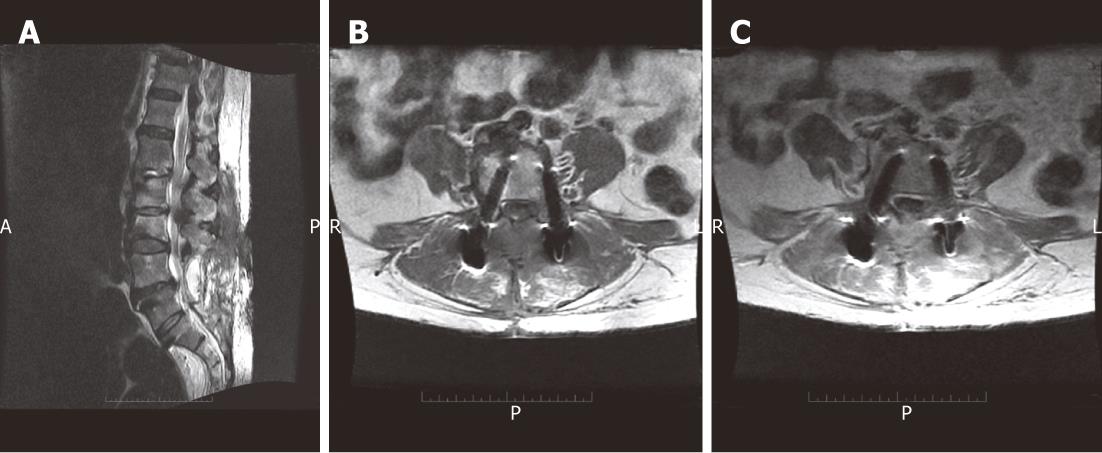
Metallic hardware-induced MR susceptibility artifacts are mainly the sum of local field inhomogenities (due to spin resonance differences between metal and surrounding soft-tissues) altering both phase and frequency of local spins. These result in subsequent image formation misregistration in the form of signal loss within the metallic object, distortion of the shape of the metallic object along the axes of frequency encoding and section selection as well as high signal intensity appearing around the metallic object (Figure 6A)[59-62].
As mentioned with CT, the production of metal-related artifacts in MRI is a result of both hardware-related factors such as hardware composition, geometry (shape), as well as location (orientation to the main magnetic fields) and MRI technical factors including magnetic field strength used, type of pulse sequences applied and the sequence parameters, including voxel size (determined by field of view, image matrix, and section thickness), and echo train length[62-64].
Paying attention to patient positioning, choosing adequate imaging parameters and selecting different pulse sequences will help to reduce MR susceptibility artifacts associated with the spinal hardware and optimize the clinical value of MRI in such patient groups.
Again, hardware-related factors are beyond the control of the imager. Non-ferromagnetic titanium and polycarbon-enforced implants produce fewer severe artifacts than do ferromagnetic implants made of stainless steel. Also, the larger the implant size the more obtrusive the artifact will be[47,62,65-67].
In spite of multiple components and directions of the spinal hardware, alignment of the longitudinal axis of the hardware device parallel to the direction of the main magnetic field (z-axis of the scanner), will significantly reduce the resultant artifact[47,62,66-68].
The quality of MR images is dependent on the pulse sequence parameters used. Routine techniques used in the preoperative setting cannot be employed in the postoperative setting, as the resultant metal artifact is too great, yielding non-diagnostic images[56].
High-field-strength magnets produce larger magnetic susceptibility artifacts as misregistration artifacts are proportional to the magnitude of the local inhomogeneity in the main magnetic field, while it is inversely proportional to the strength of the applied frequency-encoding gradient[47,68,69].
However, the increased distortion effects of a higher main magnetic field strength could be offset by higher gradient strengths[70]. Another advantage of high-field magnets is the use of broad-band width receivers that can reduce these magnetic susceptibility artifacts[47,62].
Gradient strength depends on selected field of view and matrix size in a given pulse sequence. This implies that the smaller the voxel, the smaller the artifact[66]. Hence, the use of a small field of view, high-resolution matrix (e.g., 256 × 256 or 512 × 512), thin section, and high gradient strength can help reduce metal-related artifacts[47,71].
Gradient recalled echo (GRE) sequences are extremely sensitive to the presence of metal due to intravoxel dephasing resulting in signal loss seen as a dark or black area around the metal on the processed images (Figure 6B). This could be reduced by shortening the echo time (TE) and decreasing voxel size to minimize intravoxel dephasing seen on GRE acquisition[47,62,64,69,72].
In contrast to GRE sequences, use of a 180° refocusing pulse with SE and FSE sequences, enables recovery of the transverse signal lost due to static magnetic field inhomogenities and bulk susceptibility differences, to some extent[66,72].
The magnetic field inhomogenities adjacent to ferromagnetic materials causes increased dephasing per unit distance of travel in randomly diffusing spinning protons (T2-effect) augmenting signal loss on imaging the orthopedic hardware, prominently on long TE (T2-weighted) acquisition sequences[69]. This could be overcome by using FSE images with decreased inter-echo spacing (↓TE) in the same echo-train duration i.e., increasing echo-train length, thus reducing diffusion-related signal loss during filling the K-space and improves the resultant image[62,73,74].
Variation of the regional magnetic field surrounding metallic devices or debris creates an inhomogeneous magnetic field, augmenting metal-induced signal loss and making use of frequency-selective fat saturation poor choice for depicting marrow lesions and optimizing contrast studies in patients with metallic hardware[72].
An alternative method for fat suppression is the use of short inversion time inversion recovery imaging which is less dependent on the homogeneity of the main magnetic field[47,61,69]. However, decreased signal-to-noise ratio with loss of tissue signal resolution and grainy appearance of final images is a compromise[52,75].
Lee et al[76] and Potter et al[77] described a ‘view angle tilting’ technique to decrease metallic artifacts by the application of a ‘‘compensatory gradient’’ during imaging acquisitions, to correct for inhomogeneous perturbations in the local magnetic field in the vicinity of a metallic device. This results in image blurring across the entire imaging field of view, which must be partially compensated for by imaging parameter alterations such as increased receiver bandwidth, readout gradient strength, and reduced voxel size to diminish the overall decrease in signal to noise ratio (SNR) of the resultant image.
Another MRI method for nulling metallic artifacts addressed with little SNR compromise known as single-point imaging (SPI) employs several milliseconds for signal preparation and acquisition. It acquires only the immediate free induction decay following off excitation pulses to avoid diffusion-related components of metallic artifact induction. Hence, SPI requires large gradient amplitudes and long scanning times[62,78].
Bone scintigraphy including single-photon emission CT (SPECT) can assess fusion sites (the fused segment should be “cold” after 6-12 mo) and help in infection detection in the region of metal implants; especially helpful in those cases in which MRI cannot be performed or is non-diagnostic[79-82].
Radionuclide scans may remain positive for a year or more in the region of the operative bed and instrumentation due to continued normal bony remodeling at the fusion site[4,6,9,81,82].
However, very focal intense activity may reflect the presence of non-union (pseudo-arthrosis), as opposed to more ill-defined or diffuse activity that reflects normally increased bone turnover in a fused spine[7]. Combined technetium and labeled white blood cell studies may be useful for evaluating infection[7,9,81,82]. The accuracy of this dual radiotracer technique exceeds 90%[81,82].
Generally, bone scans are more sensitive and less specific than plain radiographs and cross-sectional imaging[7].
Nowadays, myelography is only justified in cases with old stainless hardware, non-diagnostic MR and unexplained neurogenic symptoms. However, after lumbar spine instrumentation, puncture of the lumbar thecal sac may be difficult due to anatomic distortion (e.g., scarring, removal of posterior elements, and addition of bone graft material) or the presence of metallic implants. Occasionally, a cervical puncture is a good alternative to the classic lumbar approach in this situation. Oblique views on conventional myelography may be needed to avoid obscuration of the relevant nerve roots by the implanted devices. It may sometimes be supplemented by MDCT myelographic evaluation[4].
Fluoroscopically, US or CT-guided anesthetic injections may be used to determine the source of pain around a prosthesis, e.g., a hook site, facet joint, or disc or in a suspected pseudo-arthrosis region. Relief of pain after anesthetic injection confirms the source of pain and allows for proper selection of treatment options. Aspiration of osseous, disc, or soft tissue lesions is also useful when infection is suspected[6,9]. Table 2 summarizes the different imaging techniques used for evaluation of spinal hardware as well as the main indications for their use.
| Technique | Indications |
| Radiographs | Instrument failure, infection, failed fusion |
| Fluoroscopic positioned spot views | Instrument position |
| Radionuclide scans/PET | Infection |
| Ultrasonography | Fluid collections, abscesses |
| CT | Instrument position, pseudo-arthrosis, infection, fragments in spinal canal, vertebral alignment |
| MR imaging | Infection, failed back, recurrent disc, recurrent tumor |
| Diagnostic injection/aspiration | Confirm source of pain, aspiration of pseudo-bursae or organisms for infection |
Inter-body fusion may be carried out with cortical bone and autogenous grafting or with inter-body fusion cages. Radiolucent disc spacers contain two radiopaque markers enabling their recognition on postoperative radiographs[3,4,6,7].
In the early postoperative period, metal cages appeared to “float” within the intervertebral space on AP plain films as morselized autografts placed within and/or around them are not visible on plain X-rays. In intact fusions, the outlines of radiolucent cages become increasingly apparent as the adjacent bone graft consolidates over time with no adjacent lucency or sclerosis[3,4,6,7].
A well-positioned spacer will show a posterior marker located at least 2 mm anterior to the adjacent posterior vertebral body margin (Figure 4B). This imaging appearance will exclude ramp/cage protrusion into the spinal canal[3,4,6,7].
The design characteristics of these devices are variable. However, both radiography and CT are equally used for evaluation of their positioning. Ideally, the device has to be located midline between the two pedicles on AP radiographs or axial or coronal CT scans and should not penetrate adjacent end plates. With respect to AP positioning, the center of rotation should be located in the posterior half of the disk space yet it should not extend beyond the posterior vertebral body line[83-85].
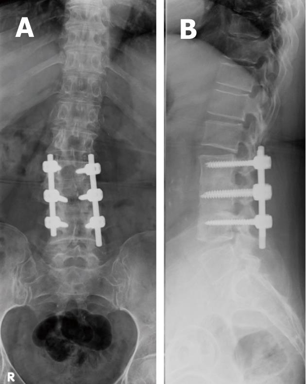
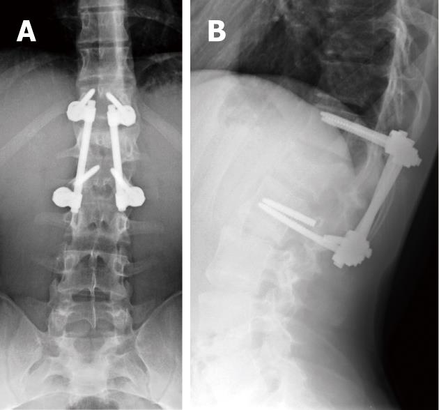
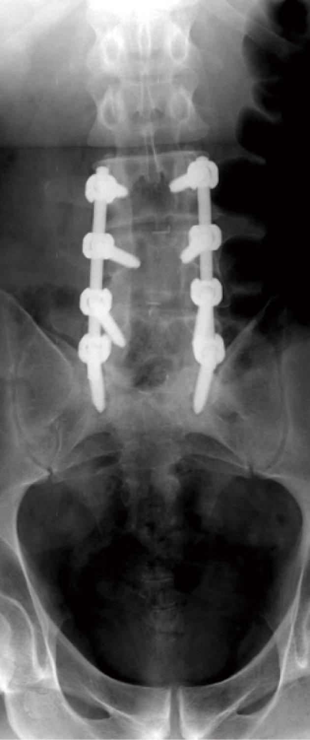
Combinations of plates and/or rods with pedicle screws are interconnected for spinal instrumentation, till bony fusion ensues. Optimal screw placement is typically along the medial aspect of the pedicle and contained within the pedicle. There is no consensus on their optimal length (> 50% of its length within the vertebral body) yet it should not break through the integrity of adjacent cortices or end-plates (Figure 5). However, sacral screws may be anchored in the anterior cortex of the sacrum for additional stability[3,4,6,7].
Screw position and fracture can usually be detected on radiographs for optimal positioning (Figure 5) or inadvertent insertion (Figure 7A and B). However, CT and/or MRI will show this more clearly with the added advantage of evaluating the status of bone graft and excluding pseudo-arthrosis[3,4,6,7].
Posterior fusion is characterized by autografts placed along decorticated facets and/or laminae[3,4,5,7,9].
The early postoperative radiographic appearances are quite variable, sometimes it shows large solid fusion masses, and other times, small wispy bone grafts hardly show up on plain X-ray and/or on CT, particularly if small amounts of graft were placed along the posterior elements and/or transverse processes (Figure 8)[3,6,7,9]. This gradually consolidates over several months into a solid bony fusion within 9-12 mo postoperatively, if successful fusions have ensued[3,6,7,9].
These are commonly seen following ACDF procedures, scoliosis corrective surgery and/or following vertebral corpectomy at any spinal level. These devices are commonly located anteriorly spanning two to three segments in cervical regions, and are located more antero-laterally spanning longer segments in the dorsal and lumbar levels (Figure 9)[5-8,13].
Anterior plates are anchored to the underlying vertebral bodies with screws, which should enter the anterior cortex of each vertebral body and be seated in the posterior cortex without impinging on the cord for firm purchase of the screws to promote posterior graft material compression and enhance bony fusion. Ideally, the screws should not enter an adjacent end plate and should be at least 2 mm from the superior and inferior end plates[5-8,13].
Usually, the intervertebral disks are removed and replaced with bone graft material for anterior spinal fusion. Sometimes, these devices are supplemented with posterior fixation devices.
Given the technical difficulties of spinal instrumentation procedures, it is recognized that complications may arise from mal-positioning of hardware, technical difficulties associated with different surgical approaches, underlying clinical circumstances as well as improper patient and/or hardware selection. Imaging plays a vital role in evaluating potential complications of spinal instrumentation procedures.
Every radiologist should have his/her systematic approach to assess the integrity of the spinal hardware, neural and vascular structures throughout the spine, including the neural foramina, thecal sac, spinal cord and cauda equina, as well as peri-spinal anatomic regions of interest.
Broadly speaking, these complications are divided into spinal hardware-related complications, bony fusion-related complications and operative procedure-related complications.
Operative procedure level points to potential complications. Anterior cervical spine procedures may be associated with transient nerve palsies, arterial (vertebral and carotid arteries) dissections and esophageal tears[86-90]. Bone graft extrusion and instrument subsidence have also been described[90].
Anterior procedures in the thoraco-lumbar spine have a higher incidence of local complications and at the bone graft donor site. Vascular injuries are also more common[91,92]. With newer techniques, such as video-arthroscopy, thoracic duct injury and injury to the long thoracic or phrenic nerves may occur[13].
Spinal fixation and fusion are long surgical procedures; especially with increased length of the fixed spinal segments as in scoliosis; requiring prolonged immobilization or recumbency, making patients more vulnerable to certain complications such as brachial plexus injuries, superior mesenteric artery syndrome and thrombophlebitis[9,93-95].
Medical complications are also common. Genitourinary infections occur in 20% and deep venous thrombosis in 25% of patients. These problems are more common in patients who have post-traumatic paralysis or prolonged hospitalization[9]. Gastrointestinal hemorrhage may be as high as 40% in patients receiving steroid therapy[91].
The acute onset of neurologic symptoms in the immediate postoperative setting should arouse clinical suspicion about the possible formation of a hematoma, a surgical emergency that requires urgent surgical decompression[3,9].
Postoperative infections may occur in the immediate post-operative period or present latently several months after surgery. Infection may involve any tissue in the postoperative bed[96,97]. It may be the result of implantation at the time of surgery or occur later due to hematogenous spread and/or wound contamination[96,97].
Staphylococcus epidermidis and Propionibacterium acnes are the main organisms associated with implant infections[96].
Patients often present with pain, hotness, skin redness and swelling at the operative site with sinus formation draining deep collections in some cases.
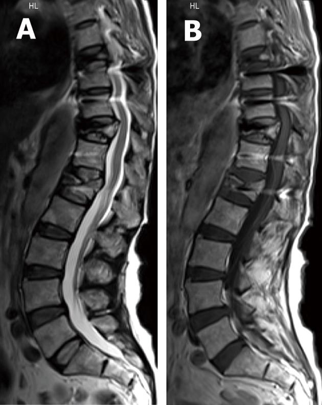
Superficial soft-tissue infections are easy to diagnose clinically. MRI may depict fluid collections, abscess formation and intense enhancement following the administration of IV gadolinium-based agents (Figure 10)[3,6,7,96,97].
CT-guided aspiration may be useful for isolating the offending organism for culturing and sensitivity tests aiding proper antibiotic selection. Implant withdrawal may be performed first if solid fusion was achieved in latent infections[3,6,7,96,97].
It should be remembered that the instrumentation used in fusion surgery is not designed to replace the bony elements of the spine, but to stabilize them as the fusion mass consolidates and takes over as the primary source of support. Any factor that retards fusion will subject the implant to abnormally high loads for longer periods and ultimately fail when it exceeds its loading capabilities[3,4,6,7,9,18,37].
Improper selection of implants may be the cause of failure, as the chosen construct may not withstand the physiologic loads imparted on it for a given patient and clinical scenario. Patients noncompliant with postoperative spinal precautions (avoiding heavy lifting, excessive bending or twisting of the trunk, or exposure to high impact activities) are liable to have their implants fail[37]. Trauma is a common cause of immediate hardware failure[6,7,37].
Associated medical conditions may predispose to hardware failure e.g., patients with metabolic bone disease or severe osteopenia may not be appropriate candidates, as their poor bone quality is associated with cutout or loosening of hardware (Figure 11)[3,4,6,7,96,98]. Morbid obesity adds to the technical difficulty of spine surgery and exerts greater stresses on instrumentation[3]. Also, smoking increases the rate of pseudo-arthrosis development after fusion[99].
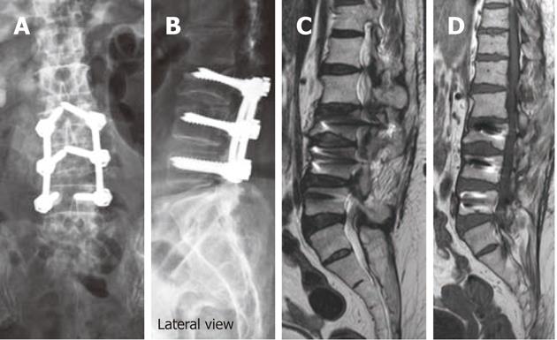
Hardware failure occurs when an implant breaks, or the device becomes largely dissociated from the underlying bone. The findings in these cases include rod migration or dislodgement, rod breakage, hook cutout or disengagement, wire breakage, screw cutout and failure (Figure 12)[37].
A precedent to hardware failure is aseptic loosening where instability due to pseudo-arthrosis and/or infection is thought to be an etiologic factor[3,4,6,7,9,18]. It is believed that particulate debris, produced by component wear, attracts and activates tissue phagocytes with repeated but unsuccessful attempts of phagocytosis to non-digestible metal particles damaging adjacent bone and cartilage by this enzymatic release resulting in osteolysis[100-102].
Based on their worldwide use and the vital structures adjacent to their insertion sites, pedicle screw complications are widely discussed in the literature. In a large series, Lonstein et al[103] reported screw fractures in 0.5%, penetration of the anterior cortex in 2.8%, pedicle fractures in 0.6%-2.7%, dural tears in 1%, and nerve root irritation in 1% (this was related to medial or inferior screw placement).
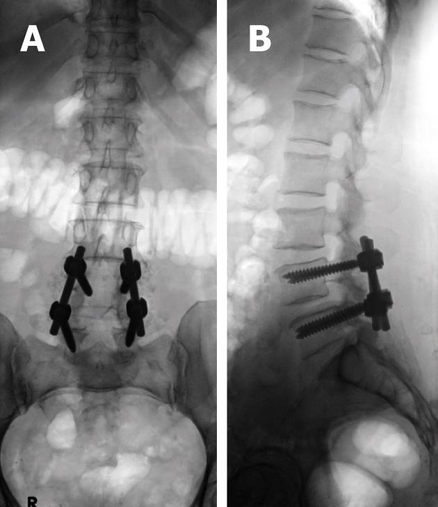
Loosening of pedicle screws appear as a rim of lucency around the screw threads (or any hardware) especially when the lucency exceeds 2 mm or increases in size on X-ray (Figure 13) and/or CT imaging follow-up[3,6,7,9]. Loose screws will often gradually retract and may eventually be expelled from the bone entirely with eventual hardware failure.
Complications may arise from medial or lateral deviation of a screw or from its penetration of the anterior cortex of the vertebral body[3,6,7,9]. When aseptic loosening is shown on imaging studies, the radiologist should look for associated failed fusion and/or infection[3,6,7,9].
Similar complications may arise from mal-positioning of anterior cervical plates and screws, which may penetrate the adjacent disk space, foramen transversarium, spinal cord, or nerve roots[3]. Inadvertent mal-positioning of cervical screws within adjacent disc material predisposes for aseptic loosening of the hardware and a high risk of vertebral body fracture as the disc material can not hold the screws[104].
Adjacent level ossification development (ALOD) was described as a long-term sequel to anterior cervical plating[3,6,9,104-106]. Park et al[105] showed the likelihood of ALOD with anterior cervical plate margin placement within 5 mm of the adjacent disk space. He concluded that any adjacent-level ossification within the first 12 mo postoperatively resulted in the likelihood of progression to advanced ossification by 24 mo in a later study[106].
Serial radiographs may be used to assess fusion using the widely accepted Ray’s[107] criteria for solid fusion recognition (Table 3).
| Ray’s criteria for radiographic assessment of bridging osseous fusion |
| Less than 3 degrees of inter-segmental position change on lateral flexion and extension views |
| No lucent area around the implant |
| Minimal loss of disk height |
| No fracture of the device, graft, or vertebra |
| No sclerotic changes in the graft or adjacent vertebra |
| Visible bone formation in or about the graft material |
A cardinal rule of hardware is that it bears a load or stress and will eventually fail unless the body fuses or heals at the site. Hence, bone grafting is used in conjunction with most spinal instrumentation procedures till solid bone graft fusion ensues within 6-9 mo and can be identified on imaging[3-9].
Subtle or low-grade instability at the fusion site results in pseudo-arthrosis or fibrous union. Pseudo-arthrosis is defined as failure of attempted spinal fusion to achieve solid bony arthrodesis by 1 year after surgery[3-9].
Pseudo-arthrosis varies widely in its incidence and etiology, being higher for ALIF (4%-68%) than the PLIF (3%-25%) and ACDF (3%-46%)[108-114]. Smoking, long-term use of non-steroidal anti-inflammatory drugs and underlying conditions such as scoliosis and osteoporosis are common risk factors for its development[108-114].
Pseudo-arthrosis or fibrous union itself may be a source of pain generation and its early recognition is critical to prevent instrument failure and allow early repair[40,93]. Mature pseudo-arthrosis appears as a clearly linear lucency across the graft material with sclerosis on its margin on radiographic films[3,6,7,9,40,108]. The same imaging findings are seen on MDCT examinations with its high-resolution and multi-planar capabilities. In addition, CT may allow precise definition of cortical margins and residual graft material[3,6,7,9,40]. With newer titanium and cobalt-chromium implants MRI can depict focal high signal intensity in the region of pseudo-articulation on T2-weighted images and bands of low intensity on T1-weighted images. Reactive marrow changes and enhancement with gadolinium due to abnormal motion may also be seen[3,6,7,9].
In the early stages of pseudo-arthrosis with equivocal radiographic examination, increased radiotracer uptake is expected at sites of motion 6-9 mo after operation as mentioned earlier[7]. SPECT of the spine showed value in detecting painful pseudo-arthrosis in patients after spinal fusion surgeries[109].
Fluoroscopically, US or CT-guided anesthetic injections are recommended by some groups to prove or disprove pseudo-arthrosis as the source of pain. A combination of buffered 1% lidocaine and 0.25% bupivacaine can be used for diagnostic injections. Bupivacaine is longer acting and allows for patient testing to determine the degree of pain relief[3,9].
Successful spinal fusion permanently alters the mechanics of vertebral segments at adjacent levels resulting in accelerated degenerative changes in the vertebrae, ligaments, and intervertebral disks[3,7,9,28,29]. These degenerative changes are termed junctional failure or adjacent segment disease[3,7,9,28,29,115-117].
This was recognized in some series as early as 3 mo post-fusion and as late as 13 years[117,118].
Junctional failure is commonly seen in the lumbar region compared with other regions, with an increased number of fused segments and with residual sagittal deformities on early postoperative upright radiographs[117,119,120].
Increasing disc height loss, degeneration, disc bulge and/or protrusions as well as progressive facet arthropathies are common and predictive for evolving junctional failure on different imaging modalities with the emphasis on comparing serial examination for accurate judgment. Micro-trauma to the intervertebral disks at adjacent levels of fusion can be a source for pain, although the disc is morphologically intact on MRI and/or myelographic examinations[3,117,119,120].
Adjacent vertebral body fractures and collapse have been reported especially in osteoporotic cases[117,121].
In conclusion, radiologists are required to be familiar with the instrumentation and operative options used in spinal fixation and fusion procedures to properly assess outcome, as it forms an increasing bulk of daily practice in a busy imaging department. The goal of spinal instrumentation is to maintain or correct anatomic alignment of spinal segments by sharing the loads acting on the spine, usually until a solid biological fusion occurs.
Familiarity with the different forms of instrumentation, fusion approaches and expected results is critical in evaluating the position of implants and potential complications associated with the operative approaches and spinal fixation devices used. Thus, the radiologist can play an important role in patient care and outcome.
Baseline radiographs are essential as the baseline point for evaluation of future studies should patients develop symptoms suggesting possible complications. They may justify further imaging workup with CT, MR and/or nuclear medicine studies, as evaluation of a patient with a spinal implant involves a multi-modality approach. This review outlines basic knowledge to help radiologists to approach everyday practice in clinical imaging.
I thank Dr. Abass Nour El-Din, Professor of Radiology, El-Menia University, Egypt, for his preliminary review of the manuscript
| 2. | Albee FH. Transplantation of a portion of the tibia into the spine for Pott’s disease. JAMA. 1911;57:855. |
| 3. | Young PM, Berquist TH, Bancroft LW, Peterson JJ. Complications of spinal instrumentation. Radiographics. 2007;27:775-789. [PubMed] |
| 4. | Rutherford EE, Tarplett LJ, Davies EM, Harley JM, King LJ. Lumbar spine fusion and stabilization: hardware, techniques, and imaging appearances. Radiographics. 2007;27:1737-1749. [PubMed] |
| 5. | Slone RM, McEnery KW, Bridwell KH, Montgomery WJ. Fixation techniques and instrumentation used in the thoracic, lumbar, and lumbosacral spine. Radiol Clin North Am. 1995;33:233-265. [PubMed] |
| 6. | Berquist TH. Imaging of the postoperative spine. Radiol Clin North Am. 2006;44:407-418. [PubMed] |
| 7. | im PE, Zee CS. Imaging of the postoperative spine: cages, prostheses, and instrumentation. Spinal imaging: Diagnostic imaging of the spine and spinal cord. Berlin: Springer 2007; 397-413. |
| 8. | Slone RM, McEnery KW, Bridwell KH, Montgomery WJ. Fixation techniques and instrumentation used in the cervical spine. Radiol Clin North Am. 1995;33:213-232. [PubMed] |
| 9. | Berquist TH. Spinal instrumentation. Imaging of orthopedic fixation devices and prostheses. Philadelphia, PA: Lippincott Williams and Wilkins 2009; 75-152. |
| 10. | Sharma M, Langrana NA, Rodriguez J. Role of ligaments and facets in lumbar spinal stability. Spine (Phila Pa 1976). 1995;20:887-900. [PubMed] |
| 11. | American Academy of Orthopaedic Surgeons. A glossary on spinal terminology. Chicago: American Academy of Orthopaedic Surgeons 1985; . |
| 12. | Denis F. The three column spine and its significance in the classification of acute thoracolumbar spinal injuries. Spine (Phila Pa 1976). 1983;8:817-831. [PubMed] |
| 13. | Crawford AH. Anterior surgery in the thoracic and lumbar spine: endoscopic techniques in children. J Bone Joint Surg Am. 2004;86:2752-2763. |
| 14. | Peterson LE, Nachemson AL. Prediction of progression of the curve in girls who have adolescent idiopathic scoliosis of moderate severity. Logistic regression analysis based on data from The Brace Study of the Scoliosis Research Society. J Bone Joint Surg Am. 1995;77:823-827. [PubMed] |
| 15. | Hanley EN, David SM. Lumbar arthrodesis for the treatment of back pain. J Bone Joint Surg Am. 1999;81:716-730. [PubMed] |
| 16. | McAfee PC. Interbody fusion cages in reconstructive operations on the spine. J Bone Joint Surg Am. 1999;81:859-880. [PubMed] |
| 17. | Paul SD, Vincent TC, Kaut EM, Vijay GK. Cervical spine construct design. Spine surgery: techniques, complication avoidance and management. Philadelphia (PA), USA, Elsevier-Churchill Livingstone; 2005; 1596-1608. |
| 18. | Krag MH. Spinal fusion overview of options and posterior internal fixation devices. The adult spine: principles and practice. New York: Raven Press 1991; 1919-1945. |
| 19. | Burkus JK, Gornet MF, Dickman CA, Zdeblick TA. Anterior lumbar interbody fusion using rhBMP-2 with tapered interbody cages. J Spinal Disord Tech. 2002;15:337-349. [RCA] [PubMed] [DOI] [Full Text] [Cited by in Crossref: 547] [Cited by in RCA: 476] [Article Influence: 19.8] [Reference Citation Analysis (0)] |
| 20. | Kim SH, Shin HC, Shin DA, Kim KN, Yoon do H. Early clinical experience with the mobi-C disc prosthesis. Yonsei Med J. 2007;48:457-464. [PubMed] |
| 21. | Durbhakula MM, Ghiselli G. Cervical total disc replacement, part I: rationale, biomechanics, and implant types. Orthop Clin North Am. 2005;36:349-354. [PubMed] |
| 22. | Frelinghuysen P, Huang RC, Girardi FP, Cammisa FP. Lumbar total disc replacement part I: rationale, biomechanics, and implant types. Orthop Clin North Am. 2005;36:293-299. [PubMed] |
| 23. | Sekhon LH, Ball JR. Artificial cervical disc replacement: principles, types and techniques. Neurol India. 2005;53:445-450. [PubMed] |
| 24. | Fernström U. Arthroplasty with intercorporal endoprothesis in herniated disc and in painful disc. Acta Chir Scand Suppl. 1966;357:154-159. [PubMed] |
| 25. | Bao QB, McCullen GM, Higham PA, Dumbleton JH, Yuan HA. The artificial disc: theory, design and materials. Biomaterials. 1996;17:1157-1167. [RCA] [PubMed] [DOI] [Full Text] [Cited by in Crossref: 165] [Cited by in RCA: 127] [Article Influence: 4.2] [Reference Citation Analysis (0)] |
| 26. | Yang YC, Nie L, Cheng L, Hou Y. Clinical and radiographic reports following cervical arthroplasty: a 24-month follow-up. Int Orthop. 2009;33:1037-1042. [PubMed] |
| 27. | Yajun W, Yue Z, Xiuxin H, Cui C. A meta-analysis of artificial total disc replacement versus fusion for lumbar degenerative disc disease. Eur Spine J. 2010;19:1250-1261. [PubMed] |
| 28. | Harrop JS, Youssef JA, Maltenfort M, Vorwald P, Jabbour P, Bono CM, Goldfarb N, Vaccaro AR, Hilibrand AS. Lumbar adjacent segment degeneration and disease after arthrodesis and total disc arthroplasty. Spine (Phila Pa 1976). 2008;33:1701-1707. [PubMed] |
| 29. | Min JH, Jang JS, Jung B, Lee HY, Choi WC, Shim CS, Choi G, Lee SH. The clinical characteristics and risk factors for the adjacent segment degeneration in instrumented lumbar fusion. J Spinal Disord Tech. 2008;21:305-309. [RCA] [PubMed] [DOI] [Full Text] [Cited by in Crossref: 72] [Cited by in RCA: 82] [Article Influence: 4.6] [Reference Citation Analysis (0)] |
| 30. | Korovessis P, Papazisis Z, Koureas G, Lambiris E. Rigid, semirigid versus dynamic instrumentation for degenerative lumbar spinal stenosis: a correlative radiological and clinical analysis of short-term results. Spine (Phila Pa 1976). 2004;29:735-742. [PubMed] |
| 31. | Nockels RP. Dynamic stabilization in the surgical management of painful lumbar spinal disorders. Spine (Phila Pa 1976). 2005;30:S68-S72. [PubMed] |
| 32. | Sapkas GS, Themistocleous GS, Mavrogenis AF, Benetos IS, Metaxas N, Papagelopoulos PJ. Stabilization of the lumbar spine using the dynamic neutralization system. Orthopedics. 2007;30:859-865. [PubMed] |
| 33. | Schwarzenbach O, Berlemann U, Stoll TM, Dubois G. Posterior dynamic stabilization systems: DYNESYS. Orthop Clin North Am. 2005;36:363-372. [PubMed] |
| 34. | Stoll TM, Dubois G, Schwarzenbach O. The dynamic neutralization system for the spine: a multi-center study of a novel non-fusion system. Eur Spine J. 2002;11 Suppl 2:S170-S178. [PubMed] |
| 35. | Rohlmann A, Burra NK, Zander T, Bergmann G. Comparison of the effects of bilateral posterior dynamic and rigid fixation devices on the loads in the lumbar spine: a finite element analysis. Eur Spine J. 2007;16:1223-1231. [PubMed] |
| 36. | Brodsky AE, Kovalsky ES, Khalil MA. Correlation of radiologic assessment of lumbar spine fusions with surgical exploration. Spine (Phila Pa 1976). 1991;16:S261-S265. [PubMed] |
| 37. | Bagchi K, Mohaideen A, Thomson JD, Foley LC. Hardware complications in scoliosis surgery. Pediatr Radiol. 2002;32:465-475. [PubMed] |
| 38. | Whitecloud TS, Skalley TC, Cook SD, Morgan EL. Roentgenographic measurement of pedicle screw penetration. Clin Orthop Relat Res. 1989;245:57-68. [PubMed] |
| 39. | Yeakley JW, Harris JH Jr. Imaging of spinal fusions. Spinal fusion, science and technique. New York: Springer 1990; 335-347. |
| 40. | Slone RM, MacMillan M, Montgomery WJ. Spinal fixation. Part 3. Complications of spinal instrumentation. Radiographics. 1993;13:797-816. [PubMed] |
| 41. | Fishman EK, Magid D, Robertson DD, Brooker AF, Weiss P, Siegelman SS. Metallic hip implants: CT with multiplanar reconstruction. Radiology. 1986;160:675-681. [PubMed] |
| 42. | New PF, Rosen BR, Brady TJ, Buonanno FS, Kistler JP, Burt CT, Hinshaw WS, Newhouse JH, Pohost GM, Taveras JM. Potential hazards and artifacts of ferromagnetic and nonferromagnetic surgical and dental materials and devices in nuclear magnetic resonance imaging. Radiology. 1983;147:139-148. [PubMed] |
| 43. | Sennst DA, Kachelriess M, Leidecker C, Schmidt B, Watzke O, Kalender WA. An extensible software-based platform for reconstruction and evaluation of CT images. Radiographics. 2004;24:601-613. [PubMed] |
| 44. | Watzke O, Kalender WA. A pragmatic approach to metal artifact reduction in CT: merging of metal artifact reduced images. Eur Radiol. 2004;14:849-856. [PubMed] |
| 45. | Golimbu C, Firooznia H, Rafii M, Engler G, Delman A. Computed tomography of thoracic and lumbar spine fractures that have been treated with Harrington instrumentation. Radiology. 1984;151:731-733. [PubMed] |
| 46. | White RR, Newberg A, Seligson D. Computerized tomographic assessment of the traumatized dorsolumbar spine before and after Harrington instrumentation. Clin Orthop Relat Res. 1980;146:150-156. [PubMed] |
| 47. | Lee MJ, Kim S, Lee SA, Song HT, Huh YM, Kim DH, Han SH, Suh JS. Overcoming artifacts from metallic orthopedic implants at high-field-strength MR imaging and multi-detector CT. Radiographics. 2007;27:791-803. [PubMed] |
| 48. | Douglas-Akinwande AC, Buckwalter KA, Rydberg J, Rankin JL, Choplin RH. Multichannel CT: evaluating the spine in postoperative patients with orthopedic hardware. Radiographics. 2006;26 Suppl 1:S97-S110. [PubMed] |
| 49. | Haramati N, Staron RB, Mazel-Sperling K, Freeman K, Nickoloff EL, Barax C, Feldman F. CT scans through metal scanning technique versus hardware composition. Comput Med Imaging Graph. 1994;18:429-434. [RCA] [PubMed] [DOI] [Full Text] [Cited by in Crossref: 89] [Cited by in RCA: 80] [Article Influence: 2.5] [Reference Citation Analysis (0)] |
| 50. | White LM, Buckwalter KA. Technical considerations: CT and MR imaging in the postoperative orthopedic patient. Semin Musculoskelet Radiol. 2002;6:5-17. [PubMed] |
| 51. | Robertson DD, Weiss PJ, Fishman EK, Magid D, Walker PS. Evaluation of CT techniques for reducing artifacts in the presence of metallic orthopedic implants. J Comput Assist Tomogr. 1988;12:236-241. [PubMed] |
| 52. | Stradiotti P, Curti A, Castellazzi G, Zerbi A. Metal-related artifacts in instrumented spine. Techniques for reducing artifacts in CT and MRI: state of the art. Eur Spine J. 2009;18 Suppl 1:102-108. [PubMed] |
| 53. | Silverman PM, Kalender WA, Hazle JD. Common terminology for single and multislice helical CT. AJR Am J Roentgenol. 2001;176:1135-1136. [PubMed] |
| 54. | Rydberg J, Liang Y, Teague SD. Fundamentals of multichannel CT. Radiol Clin North Am. 2003;41:465-474. [RCA] [PubMed] [DOI] [Full Text] [Cited by in Crossref: 41] [Cited by in RCA: 35] [Article Influence: 1.5] [Reference Citation Analysis (0)] |
| 55. | Jinkins JR, Van Goethem JW. The postsurgical lumbosacral spine. Magnetic resonance imaging evaluation following intervertebral disk surgery, surgical decompression, intervertebral bony fusion, and spinal instrumentation. Radiol Clin North Am. 2001;39:1-29. [PubMed] |
| 56. | Sofka CM, Potter HG, Adler RS, Pavlov H. Musculoskeletal imaging update: current applications of advanced imaging techniques to evaluate the early and long-term complications of patients with orthopedic implants. HSS J. 2006;2:73-77. [PubMed] |
| 57. | Krijnen MR, Smit TH, Strijkers GJ, Nicolay K, Pouwels PJ, Wuisman PI. The use of high-resolution magnetic resonance imaging for monitoring interbody fusion and bioabsorbable cages: an ex vivo pilot study. Neurosurg Focus. 2004;16:E3. [PubMed] |
| 58. | Van Goethem JW, Parizel PM, Jinkins JR. Review article: MRI of the postoperative lumbar spine. Neuroradiology. 2002;44:723-739. [PubMed] |
| 59. | Lüdeke KM, Röschmann P, Tischler R. Susceptibility artefacts in NMR imaging. Magn Reson Imaging. 1985;3:329-343. [PubMed] |
| 60. | Bakker CJ, Bhagwandien R, Moerland MA, Fuderer M. Susceptibility artifacts in 2DFT spin-echo and gradient-echo imaging: the cylinder model revisited. Magn Reson Imaging. 1993;11:539-548. [PubMed] |
| 61. | Viano AM, Gronemeyer SA, Haliloglu M, Hoffer FA. Improved MR imaging for patients with metallic implants. Magn Reson Imaging. 2000;18:287-295. [PubMed] |
| 62. | Harris CA, White LM. Metal artifact reduction in musculoskeletal magnetic resonance imaging. Orthop Clin North Am. 2006;37:349-359, vi. [PubMed] |
| 63. | Petersilge CA, Lewin JS, Duerk JL, Yoo JU, Ghaneyem AJ. Optimizing imaging parameters for MR evaluation of the spine with titanium pedicle screws. AJR Am J Roentgenol. 1996;166:1213-1218. [PubMed] |
| 64. | Port JD, Pomper MG. Quantification and minimization of magnetic susceptibility artifacts on GRE images. J Comput Assist Tomogr. 2000;24:958-964. [PubMed] |
| 65. | Eggers G, Rieker M, Kress B, Fiebach J, Dickhaus H, Hassfeld S. Artefacts in magnetic resonance imaging caused by dental material. MAGMA. 2005;18:103-111. [PubMed] |
| 66. | Suh JS, Jeong EK, Shin KH, Cho JH, Na JB, Kim DH, Han CD. Minimizing artifacts caused by metallic implants at MR imaging: experimental and clinical studies. AJR Am J Roentgenol. 1998;171:1207-1213. [PubMed] |
| 67. | Ganapathi M, Joseph G, Savage R, Jones AR, Timms B, Lyons K. MRI susceptibility artefacts related to scaphoid screws: the effect of screw type, screw orientation and imaging parameters. J Hand Surg Br. 2002;27:165-170. [PubMed] |
| 68. | Guermazi A, Miaux Y, Zaim S, Peterfy CG, White D, Genant HK. Metallic artefacts in MR imaging: effects of main field orientation and strength. Clin Radiol. 2003;58:322-328. [PubMed] |
| 69. | White LM, Kim JK, Mehta M, Merchant N, Schweitzer ME, Morrison WB, Hutchison CR, Gross AE. Complications of total hip arthroplasty: MR imaging-initial experience. Radiology. 2000;215:254-262. [PubMed] |
| 70. | Alanen A, Bondestam S, Komu M. Artifacts in MR imaging caused by small quantities of powdered iron. Acta Radiol. 1995;36:92-95. [PubMed] |
| 71. | Törmänen J, Tervonen O, Koivula A, Junila J, Suramo I. Image technique optimization in MR imaging of a titanium alloy joint prosthesis. J Magn Reson Imaging. 1996;6:805-811. [RCA] [PubMed] [DOI] [Full Text] [Cited by in Crossref: 35] [Cited by in RCA: 37] [Article Influence: 1.2] [Reference Citation Analysis (0)] |
| 72. | Mitchell DG, Cohen MS. Transverse magnetization and T2 contrast. MRI principles. 2nd ed. New York, NY: Springer-Verlag 2000; 35-47. |
| 73. | Tartaglino LM, Flanders AE, Vinitski S, Friedman DP. Metallic artifacts on MR images of the postoperative spine: reduction with fast spin-echo techniques. Radiology. 1994;190:565-569. [PubMed] |
| 74. | Hilfiker P, Zanetti M, Debatin JF, McKinnon G, Hodler J. Fast spin-echo inversion-recovery imaging versus fast T2-weighted spin-echo imaging in bone marrow abnormalities. Invest Radiol. 1995;30:110-114. [PubMed] |
| 75. | Bley TA, Wieben O, François CJ, Brittain JH, Reeder SB. Fat and water magnetic resonance imaging. J Magn Reson Imaging. 2010;31:4-18. [PubMed] |
| 76. | Lee MJ, Janzen DL, Munk PL, MacKay A, Xiang QS, McGowen A. Quantitative assessment of an MR technique for reducing metal artifact: application to spin-echo imaging in a phantom. Skeletal Radiol. 2001;30:398-401. [PubMed] |
| 77. | Potter HG, Nestor BJ, Sofka CM, Ho ST, Peters LE, Salvati EA. Magnetic resonance imaging after total hip arthroplasty: evaluation of periprosthetic soft tissue. J Bone Joint Surg Am. 2004;86-A:1947-1954. [PubMed] |
| 78. | Latta P, Gruwel ML, Volotovskyy V, Weber MH, Tomanek B. Single-point imaging with a variable phase encoding interval. Magn Reson Imaging. 2008;26:109-116. [PubMed] |
| 79. | McMaster MJ, Merrick MV. The scintigraphic assessment of the scoliotic spine after fusion. J Bone Joint Surg Br. 1980;62-B:65-72. [PubMed] |
| 80. | Schiesser M, Stumpe KD, Trentz O, Kossmann T, Von Schulthess GK. Detection of metallic implant-associated infections with FDG PET in patients with trauma: correlation with microbiologic results. Radiology. 2003;226:391-398. [PubMed] |
| 81. | Palestro CJ, Love C, Tronco GG, Tomas MB. Role of radionuclide imaging in the diagnosis of postoperative infection. Radiographics. 2000;20:1649-1660; discussion 1660-1663. [PubMed] |
| 82. | Gemmel F, Rijk PC, Collins JM, Parlevliet T, Stumpe KD, Palestro CJ. Expanding role of 18F-fluoro-D-deoxyglucose PET and PET/CT in spinal infections. Eur Spine J. 2010;19:540-551. [PubMed] |
| 83. | McAfee PC, Cunningham B, Holsapple G, Adams K, Blumenthal S, Guyer RD, Dmietriev A, Maxwell JH, Regan JJ, Isaza J. A prospective, randomized, multicenter Food and Drug Administration investigational device exemption study of lumbar total disc replacement with the CHARITE artificial disc versus lumbar fusion: part II: evaluation of radiographic outcomes and correlation of surgical technique accuracy with clinical outcomes. Spine (Phila Pa 1976). 2005;30:1576-1583; discussion E388-E390. [PubMed] |
| 84. | Marshman LA, Trewhella M, Friesem T, Rampersaud YR, Le Huec JC, Krishna M. The accuracy and validity of "routine" X-rays in estimating lumbar disc arthroplasty placement. Spine (Phila Pa 1976). 2007;32:E661-E666. [PubMed] |
| 85. | Murtagh RD, Quencer RM, Cohen DS, Yue JJ, Sklar EL. Normal and abnormal imaging findings in lumbar total disk replacement: devices and complications. Radiographics. 2009;29:105-118. [PubMed] |
| 87. | Garg R, Rath GP, Bithal PK, Prabhakar H, Marda MK. Effects of retractor application on cuff pressure and vocal cord function in patients undergoing anterior cervical discectomy and fusion. Indian J Anaesth. 2010;54:292-295. [PubMed] |
| 88. | Yee GKH, Terry AF. Esophageal penetration by an anterior cervical fixation device: a case report. Spine. 1993;18:522-527. |
| 89. | Pompili A, Canitano S, Caroli F, Caterino M, Crecco M, Raus L, Occhipinti E. Asymptomatic esophageal perforation caused by late screw migration after anterior cervical plating: report of a case and review of relevant literature. Spine (Phila Pa 1976). 2002;27:E499-E502. [PubMed] |
| 90. | Yang JJ, Yu CH, Chang BS, Yeom JS, Lee JH, Lee CK. Subsidence and nonunion after anterior cervical interbody fusion using a stand-alone polyetheretherketone (PEEK) cage. Clin Orthop Surg. 2011;3:16-23. [PubMed] |
| 91. | Haas N, Blauth M, Tscherne H. Anterior plating in thoracolumbar spine injuries. Indication, technique, and results. Spine (Phila Pa 1976). 1991;16:S100-S111. [PubMed] |
| 92. | Ghanayem AJ, Zdeblick TA. Anterior instrumentation in the management of thoracolumbar burst fractures. Clin Orthop Relat Res. 1997;335:89-100. [PubMed] |
| 93. | Foley MJ, Calenoff L, Hendrix RW, Schafer MF. Thoracic and lumbar spine fusion: postoperative radiologic evaluation. AJR Am J Roentgenol. 1983;141:373-380. [PubMed] |
| 94. | Uribe JS, Kolla J, Omar H, Dakwar E, Abel N, Mangar D, Camporesi E. Brachial plexus injury following spinal surgery. J Neurosurg Spine. 2010;13:552-558. [PubMed] |
| 95. | Geiger F, Parsch D, Carstens C. Complications of scoliosis surgery in children with myelomeningocele. Eur Spine J. 1999;8:22-26. [PubMed] |
| 96. | Richards BS. Delayed infections following posterior spinal instrumentation for the treatment of idiopathic scoliosis. J Bone Joint Surg Am. 1995;77:524-529. [PubMed] |
| 97. | Guidera KJ, Hooten J, Weatherly W, Highhouse M, Castellvi A, Ogden JA, Pugh L, Cook S. Cotrel-Dubousset instrumentation. Results in 52 patients. Spine (Phila Pa 1976). 1993;18:427-431. [PubMed] |
| 98. | Dua K, Kepler CK, Huang RC, Marchenko A. Vertebral body fracture after anterolateral instrumentation and interbody fusion in two osteoporotic patients. Spine J. 2010;10:e11-e15. [PubMed] |
| 99. | Brown CW, Orme TJ, Richardson HD. The rate of pseudarthrosis (surgical nonunion) in patients who are smokers and patients who are nonsmokers: a comparison study. Spine (Phila Pa 1976). 1986;11:942-943. [PubMed] |
| 100. | Maloney WJ, Smith RL. Periprosthetic osteolysis in total hip arthroplasty: the role of particulate wear debris. J Bone Joint Surg Am. 1995;77:1448-1461. |
| 101. | Wooley PH, Nasser S, Fitzgerald RH. The immune response to implant materials in humans. Clin Orthop Relat Res. 1996;326:63-70. [PubMed] |
| 102. | Toumbis CA, Kronick JL, Wooley PH, Nasser S. Total joint arthroplasty and the immune response. Semin Arthritis Rheum. 1997;27:44-47. [RCA] [PubMed] [DOI] [Full Text] [Cited by in Crossref: 32] [Cited by in RCA: 25] [Article Influence: 0.9] [Reference Citation Analysis (0)] |
| 103. | Lonstein JE, Denis F, Perra JH, Pinto MR, Smith MD, Winter RB. Complications associated with pedicle screws. J Bone Joint Surg Am. 1999;81:1519-1528. [PubMed] |
| 104. | Ning X, Wen Y, Xiao-Jian Y, Bin N, De-Yu C, Jian-Ru X, Lian-Shun J. Anterior cervical locking plate-related complications; prevention and treatment recommendations. Int Orthop. 2008;32:649-655. [PubMed] |
| 105. | Park JB, Cho YS, Riew KD. Development of adjacent-level ossification in patients with an anterior cervical plate. J Bone Joint Surg Am. 2005;87:558-563. [PubMed] |
| 106. | Park JB, Watthanaaphisit T, Riew KD. Timing of development of adjacent-level ossification after anterior cervical arthrodesis with plates. Spine J. 2007;7:633-636. [PubMed] |
| 107. | Ray CD. Threaded fusion cages for lumbar interbody fusions. An economic comparison with 360 degrees fusions. Spine (Phila Pa 1976). 1997;22:681-685. [PubMed] |
| 108. | Venu V, Vertinsky AT, Malfair D, Chew JB, Shewchuk J, Heran MK, Graeb DA, Street JT. Plain radiograph assessment of spinal hardware. Semin Musculoskelet Radiol. 2011;15:151-162. [PubMed] |
| 109. | Slizofski WJ, Collier BD, Flatley TJ, Carrera GF, Hellman RS, Isitman AT. Painful pseudarthrosis following lumbar spinal fusion: detection by combined SPECT and planar bone scintigraphy. Skeletal Radiol. 1987;16:136-141. [PubMed] |
| 110. | An HS, Simpson JM, Glover JM, Stephany J. Comparison between allograft plus demineralized bone matrix versus autograft in anterior cervical fusion. A prospective multicenter study. Spine (Phila Pa 1976). 1995;20:2211-2216. [PubMed] |
| 111. | Bolesta MJ, Rechtine GR, Chrin AM. Three- and four-level anterior cervical discectomy and fusion with plate fixation: a prospective study. Spine (Phila Pa 1976). 2000;25:2040-2044; discussion 2045-2046. [PubMed] |
| 112. | Emery SE, Fisher JR, Bohlman HH. Three-level anterior cervical discectomy and fusion: radiographic and clinical results. Spine (Phila Pa 1976). 1997;22:2622-2624; discussion 2625. [PubMed] |
| 113. | Mutoh N, Shinomiya K, Furuya K, Yamaura I, Satoh H. Pseudarthrosis and delayed union after anterior cervical fusion. Int Orthop. 1993;17:286-289. [PubMed] |
| 114. | Silcox DH. Laparoscopic bone dowel fusions of the lumbar spine. Orthop Clin North Am. 1998;29:655-663. [RCA] [PubMed] [DOI] [Full Text] [Cited by in Crossref: 16] [Cited by in RCA: 14] [Article Influence: 0.5] [Reference Citation Analysis (0)] |
| 115. | Turner JA, Ersek M, Herron L, Haselkorn J, Kent D, Ciol MA, Deyo R. Patient outcomes after lumbar spinal fusions. JAMA. 1992;268:907-911. [PubMed] |
| 116. | Cho KJ, Suk SI, Park SR, Kim JH, Kim SS, Choi WK, Lee KY, Lee SR. Complications in posterior fusion and instrumentation for degenerative lumbar scoliosis. Spine (Phila Pa 1976). 2007;32:2232-2237. [PubMed] |
| 117. | Etebar S, Cahill DW. Risk factors for adjacent-segment failure following lumbar fixation with rigid instrumentation for degenerative instability. J Neurosurg. 1999;90:163-169. [PubMed] |
| 118. | Schlegel JD, Smith JA, Schleusener RL. Lumbar motion segment pathology adjacent to thoracolumbar, lumbar, and lumbosacral fusions. Spine (Phila Pa 1976). 1996;21:970-981. [PubMed] |
| 119. | Lee CK, Langrana NA. Lumbosacral spinal fusion. A biomechanical study. Spine (Phila Pa 1976). 1984;9:574-581. [PubMed] |
| 120. | Yang SW, Langrana NA, Lee CK. Biomechanics of lumbosacral spinal fusion in combined compression-torsion loads. Spine (Phila Pa 1976). 1986;11:937-941. [PubMed] |
| 121. | Carpenter CT, Dietz JW, Leung KY, Hanscom DA, Wagner TA. Repair of a pseudarthrosis of the lumbar spine. A functional outcome study. J Bone Joint Surg Am. 1996;78:712-720. [PubMed] |
Peer reviewers: Ming-Yuan Tseng, MD, MPhil, MSc, MRCS, PhD, Department of Neurosurgery, Addenbrooke’s Hospital, University of Cambridge, 546 Derby Road, Wollaton Park, Nottingham NG7 2GY, United Kingdom; Shigeru Ehara, MD, Professor, Chair, Department of Radiology, Iwate Medical University School of Medicine, Morioka 020-8505, Japan
S- Editor Cheng JX L- Editor Webster JR E- Editor Zheng XM


