©2014 Baishideng Publishing Group Inc.
World J Radiol. May 28, 2014; 6(5): 169-176
Published online May 28, 2014. doi: 10.4329/wjr.v6.i5.169
Published online May 28, 2014. doi: 10.4329/wjr.v6.i5.169
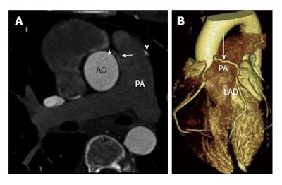
Figure 1 Coronary to pulmonary artery fistula.
A: Axial contrast enhanced coronary computed tomography angiography shows left anterior descending (LAD) artery (long arrow) and right coronary artery (arrowhead) fistulas draining into the pulmonary artery. A jet of contrast (short arrow) is seen emptying into the pulmonary artery; B: Three-dimensional volume rendered computed tomography image shows the LAD coronary artery crossing anterior to the pulmonary artery (PA) to drain into it. AO: Aorta.
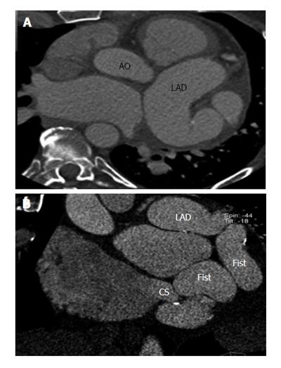
Figure 2 Left anterior descending to coronary sinus fistula.
A: Axial coronary computed tomography angiography (CTA) shows dilated, tortuous left anterior descending coronary artery (LAD); B: Sagittal reconstructed coronary CTA shows a LAD fistula draining into the coronary sinus. Fist: Fistula; CS: Coronary sinus; AO: Aorta.
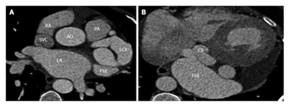
Figure 3 Left circumflex coronary artery to coronary sinus fistula.
A: Axial coronary computed tomography angiography (CTA) shows dilated, tortuous left circumflex coronary artery (LCX) due to a LCX fistula (Fist); B: Axial coronary CTA shows the LCX Fist drains into the coronary sinus (CS). PA: Pulmonary artery; AO: Aorta; LA: Left atrium; RA: Right atrium; SVC: Superior vena cava.
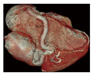
Figure 4 Right coronary artery to coronary sinus fistula.
Three-dimensional volume rendered computed tomography angiography image shows a coronary artery fistula between the right coronary artery (RCA) and the coronary sinus (CS).
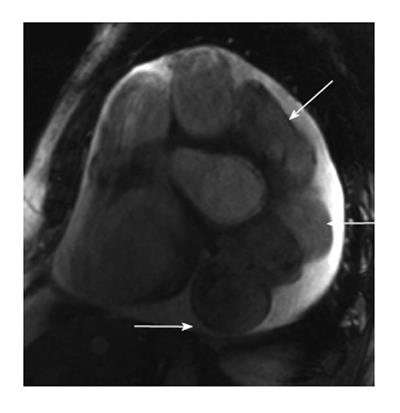
Figure 5 Magnetic resonance imaging appearances of coronary artery fistula.
Short axis steady state free precession magnetic resonance imaging image shows dilated, tortuous left anterior descending artery draining into the coronary sinus. There is also a small circumferential pericardial effusion.
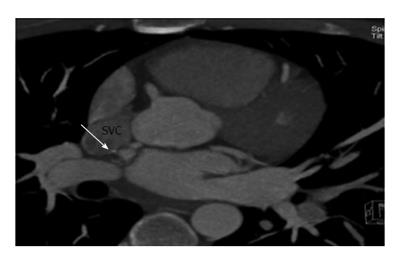
Figure 6 Right coronary artery to superior vena cava fistula.
Axial maximum intensity projection reconstruction of coronary computed tomography angiography shows a fistula (arrow) between the right coronary artery and the superior vena cava (SVC).
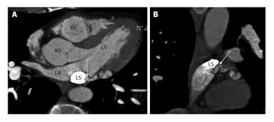
Figure 7 Left circumflex coronary artery to persistent left superior vena cava fistula.
A: Axial coronary computed tomography angiography (CTA) image shows a fistulous connection (F) between left circumflex artery and a persistent left left circumflex coronary artery (LS) which eventually drained into the coronary sinus; B: Sagittal coronary CTA reconstructed images shows fistula (arrow) between the left circumflex artery and persistent left superior vena cava (LS). AO: Aorta; LA: Left atrium.
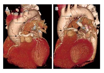
Figure 8 Complex coronary artery fistula.
A and B: 3D volume rendered coronary computed tomography angiography shows an arterial-arterial fistula originating from the proximal right coronary artery and 1st diagonal branch, which terminates in the pulmonary artery. The plexus has an aneurysmal segment that wraps around the anterior aspect of the main pulmonary artery. There is direct communication between the aneurysmal segment and the leftward aspect of the proximal MPA. Also, there are multiple smaller branches around the aortic root, MPA, ascending aorta, and transverse arch. A branch originating from the aortic arch continuous with a small 1.8-cm contrast-filled cavity adjacent to the aortic arch, between the trachea and aortic arch.
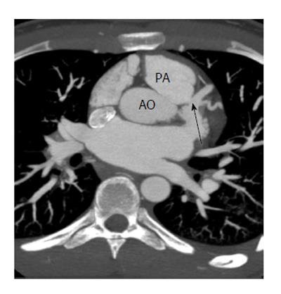
Figure 9 Anomalous origin of the left coronary artery from the pulmonary artery.
Axial MIP image shows origin of the left coronary artery (arrow) from the main pulmonary artery. PA: Pulmonary artery; AO: Aorta.
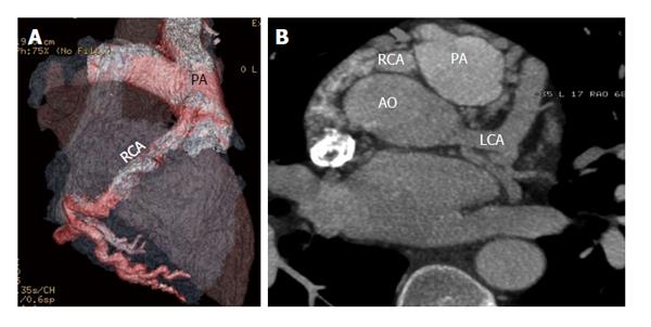
Figure 10 Anomalous origin of the right coronary artery from the pulmonary artery.
A: reconstructed computed tomography angiography (CTA) image shows origin of the right coronary artery (RCA) from the main pulmonary artery (PA); B: Axial coronary CTA shows the origin of the RCA from the pulmonary artery. To compensate for this there is dilated left coronary artery (LCA), which provides collateral supply to the RCA circulation. AO: Aorta.
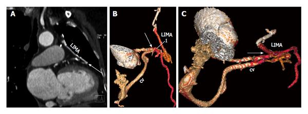
Figure 11 Coronary artery bypass graft to cardiac vein fistula.
A: Coronal coronary computed tomography angiography image shows a fistulous communication (arrow) between the left internal mammary artery (LIMA) graft and the great cardiac vein (CV); B: 3D volume rendered computed tomography (CT) image shows fistulous communication (arrow) between the LIMA graft and the great CV; C: Axial oblique reconstructed 3D volume rendered CT image demonstrates the fistulous communication (arrow).
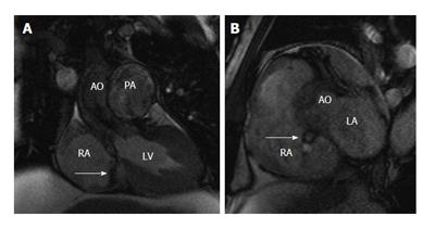
Figure 12 Aorta to right atrium fistula.
A: Coronal state free precession (SSFP) magnetic resonance imaging (MRI) image in a patient with bicuspid aortic valve and infective endocarditis shows a fistulous communication between the aorta (AO) and the right atrium (RA), with a jet of abnormal flow (arrow) demonstrated between the aorta and the right atrium; B: Sagittal short axis SSFP MRI image in the same patient shows the fistulous connection (arrow) between the aorta and the right atrium. LA: Left atrium.
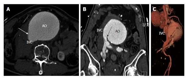
Figure 13 Aorta to inferior vena cava fistula.
A: Axial contrast computed tomography (CT) of the abdomen in a patient with history of abdominal aortic aneurysm (AO) shows similar contrast opacification of the inferior vena cava (IVC). There is a communication demonstrated (arrow) between the aorta and IVC; B: Coronal contrast CT of the abdomen demonstrates the site of fistulous communication between the aorta and the distal IVC adjacent to the right common iliac vein; C: Volume rendered 3D computed tomography angiography shows fistulous communication (arrow) between the abdominal aorta and IVC.
- Citation: Ghandour A, Rajiah P. Unusual fistulas and connections in the cardiovascular system: A pictorial review. World J Radiol 2014; 6(5): 169-176
- URL: https://www.wjgnet.com/1949-8470/full/v6/i5/169.htm
- DOI: https://dx.doi.org/10.4329/wjr.v6.i5.169


