Copyright
©The Author(s) 2019.
World J Gastroenterol. Jan 7, 2019; 25(1): 1-41
Published online Jan 7, 2019. doi: 10.3748/wjg.v25.i1.1
Published online Jan 7, 2019. doi: 10.3748/wjg.v25.i1.1
Figure 1 Kenneth J Chang, MD, FACG, FASGE.
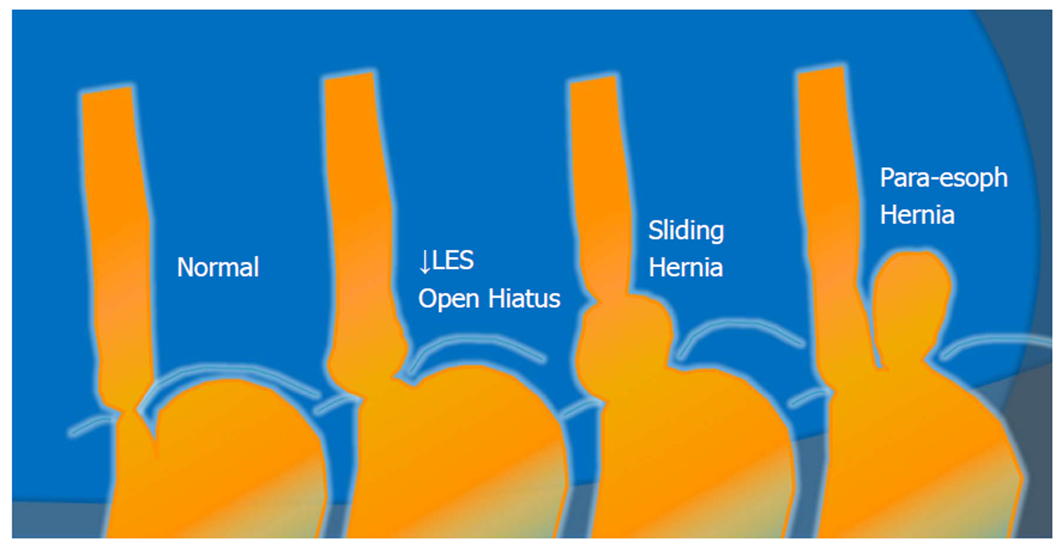
Figure 2 Anatomic spectrum of gastroesophageal reflux disease.
LES: Lower esophageal sphincter.
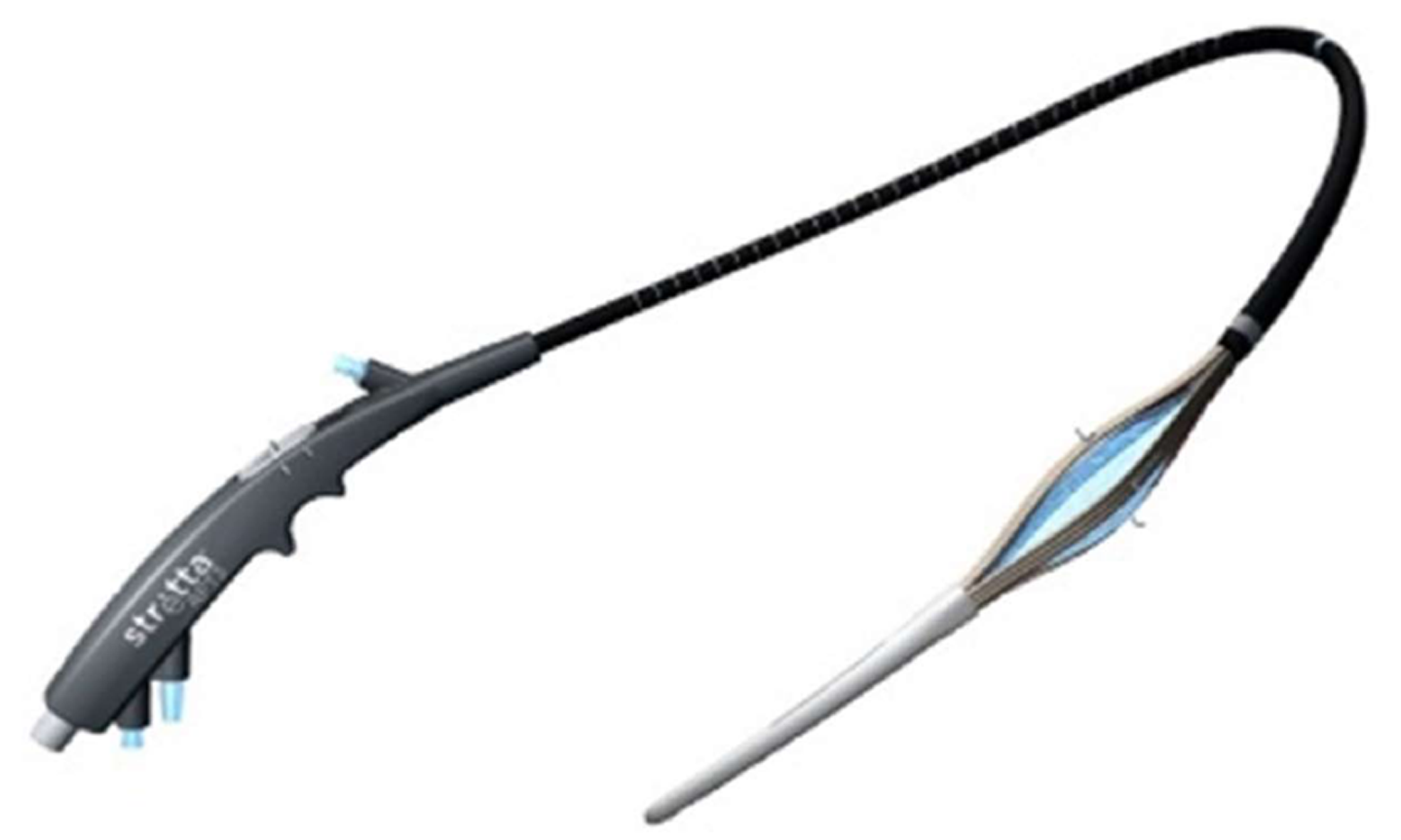
Figure 3 Stretta radiofrequency catheter.
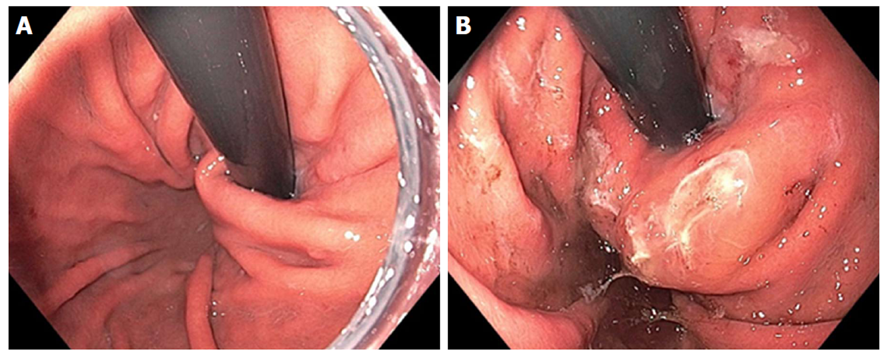
Figure 4 Endoscopic retroflex image of esophageal gastric junction prior to Stretta (A) and after Stretta treatment (B).
The esophageal gastric junction and cardia have a typical “swollen lip” appearance.
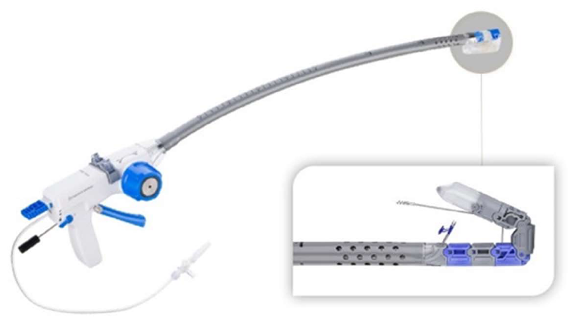
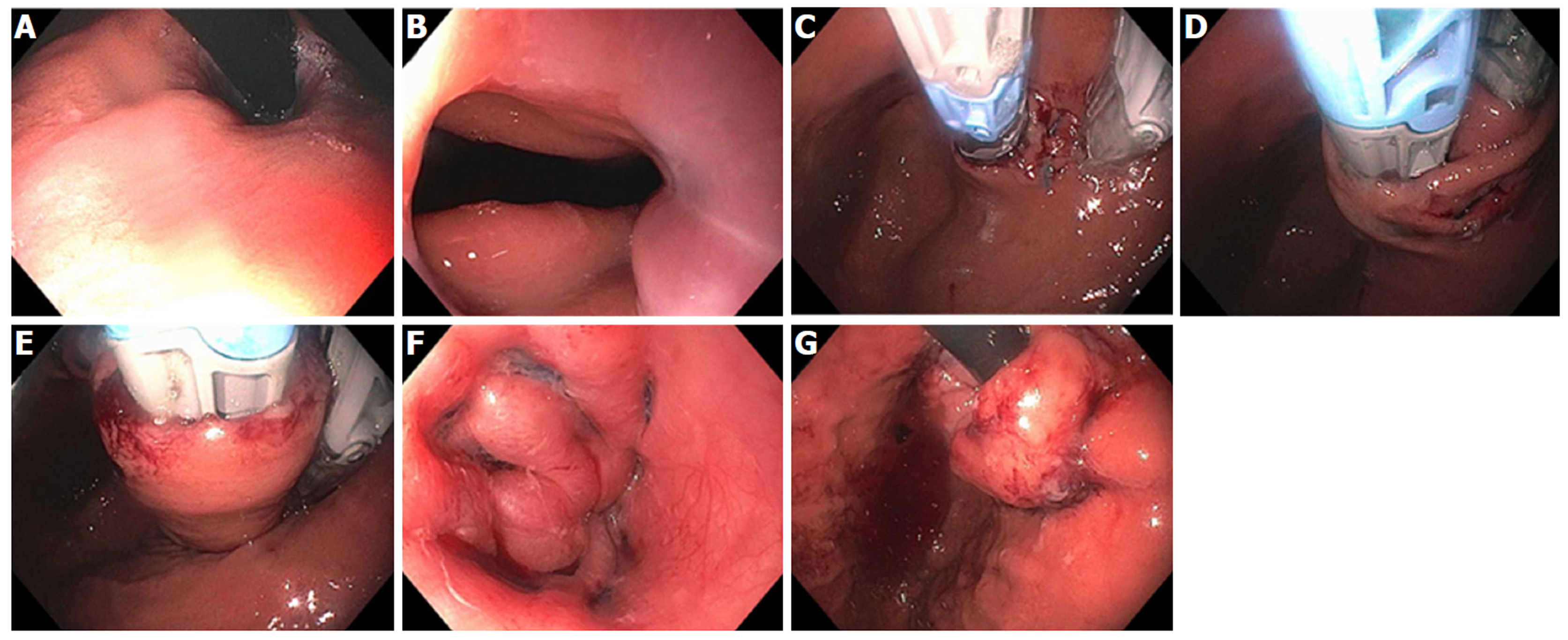
Figure 5 Esophyx® Z device used for transoral incisionless fundoplication.
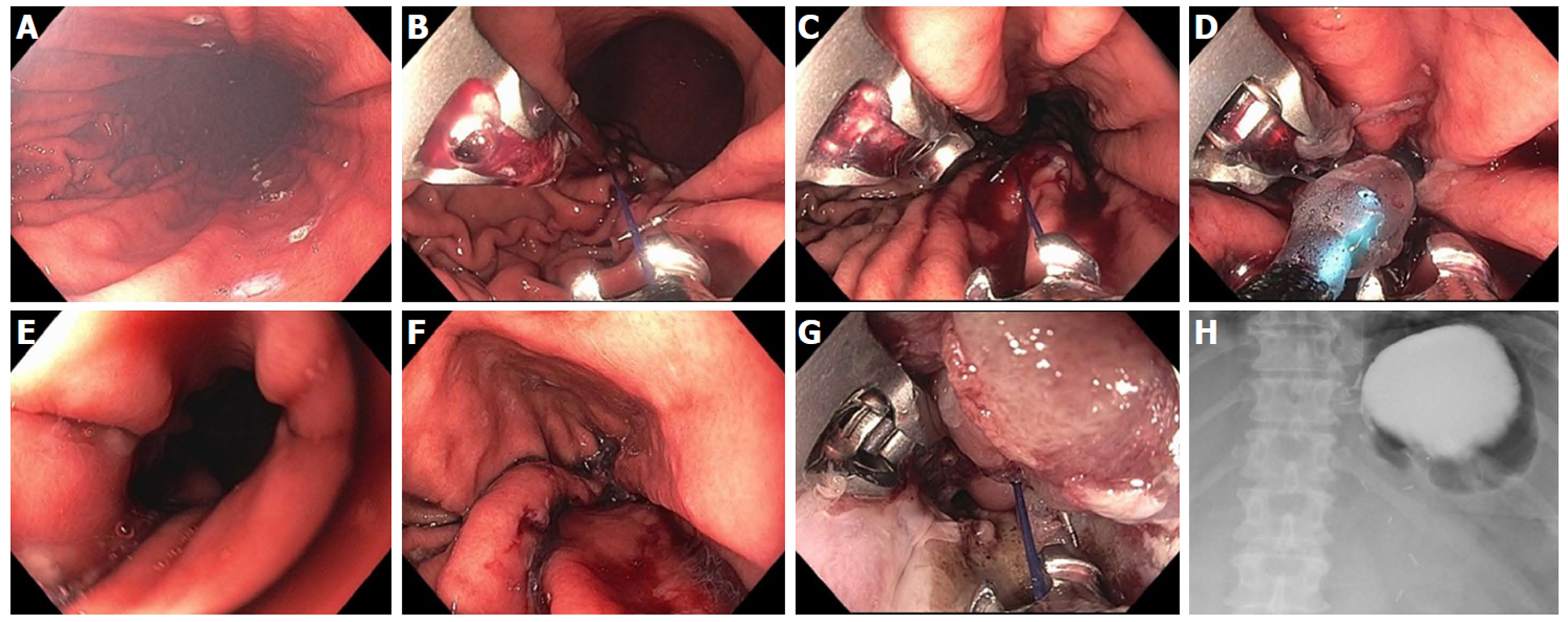
Figure 6 Transoral incisionless fundoplication 2 technique.
A: Baseline Hill Grade 2 Valve; B: Baseline patulous lower esophageal sphincter; C: Building short lip valve along lesser curve at 12 o’clock; D: Rotating the device clockwise to create a partial fundoplication on the posterior side; E: Rotating the device counter-clockwise to create a partial fundoplication on the anterior side; F: After placement of 36 fasteners, a 3-4 cm length flap valve is created; G: Fasteners can be seen extending 3-4 cm in the distal esophagus.
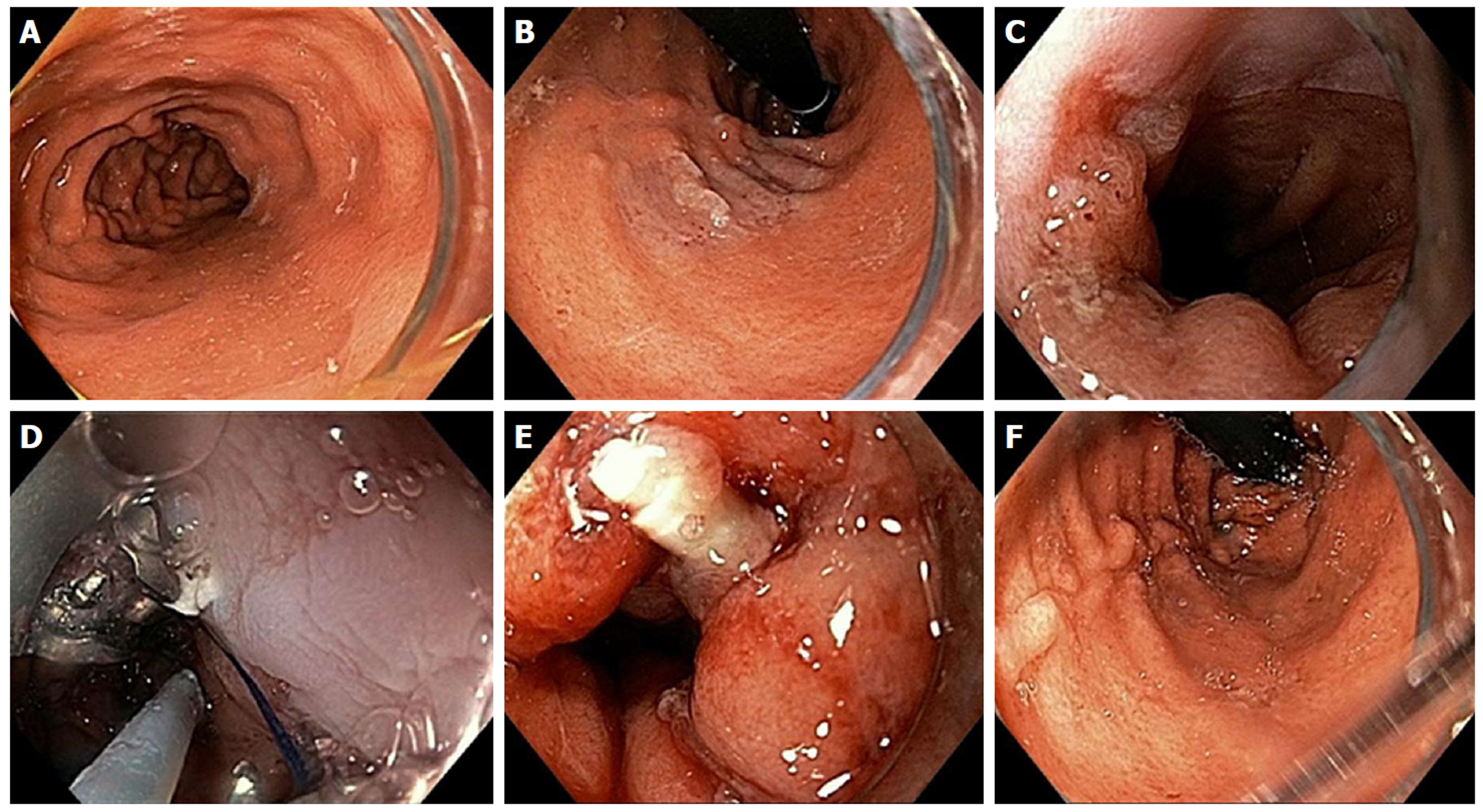
Figure 7 Endoscopic Suturing for gastroesophageal reflux disease in a patient post-Sleeve gastrectomy.
A: Narrowed gastric body post gastrectomy; B: Retroflex view of loose esophageal gastric junction (EGJ); C: Patulous lower esophageal sphincter (LES); D: Suturing at EGJ; E: Post-suturing with tightened LES; F: Retroflex view of tightened EGJ post-suturing.
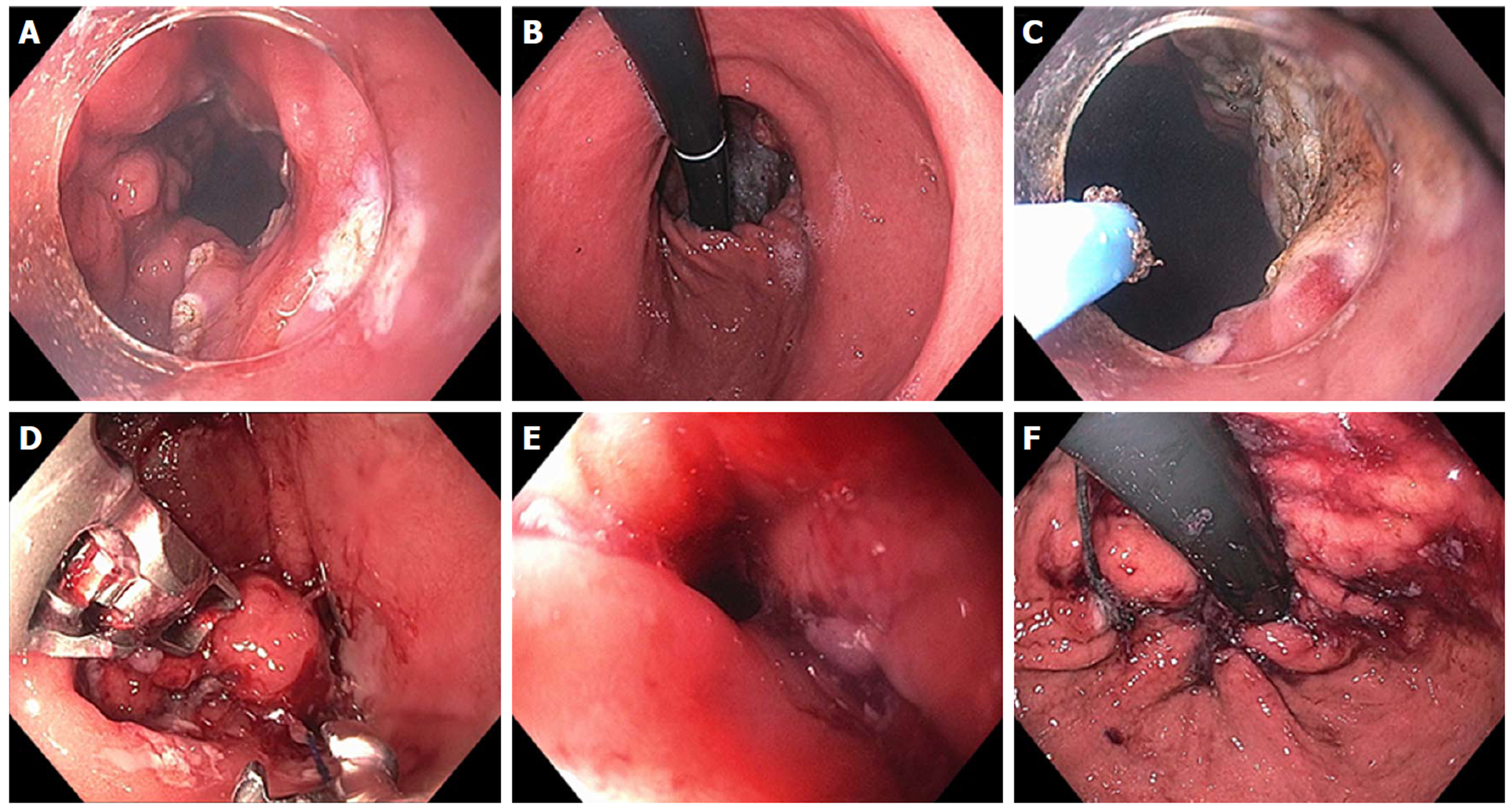
Figure 8 Mucosal ablation and suturing of the esophageal gastric junction in a patient with gastroesophageal reflux disease post-esophagectomy.
A: Wide open anastomosis along with unchecked reflux; B: Retroflex view showing open anastomosis; C: Ablation of gastric mucosa at the anastomosis using argon plasma coagulation; D: Suturing at the anastomosis; E: Post-mucosal ablation and suturing of the esophageal gastric junction (MASE) tightening of anastomosis; F: Post-MASE retroflex view showing tightened anastomosis.
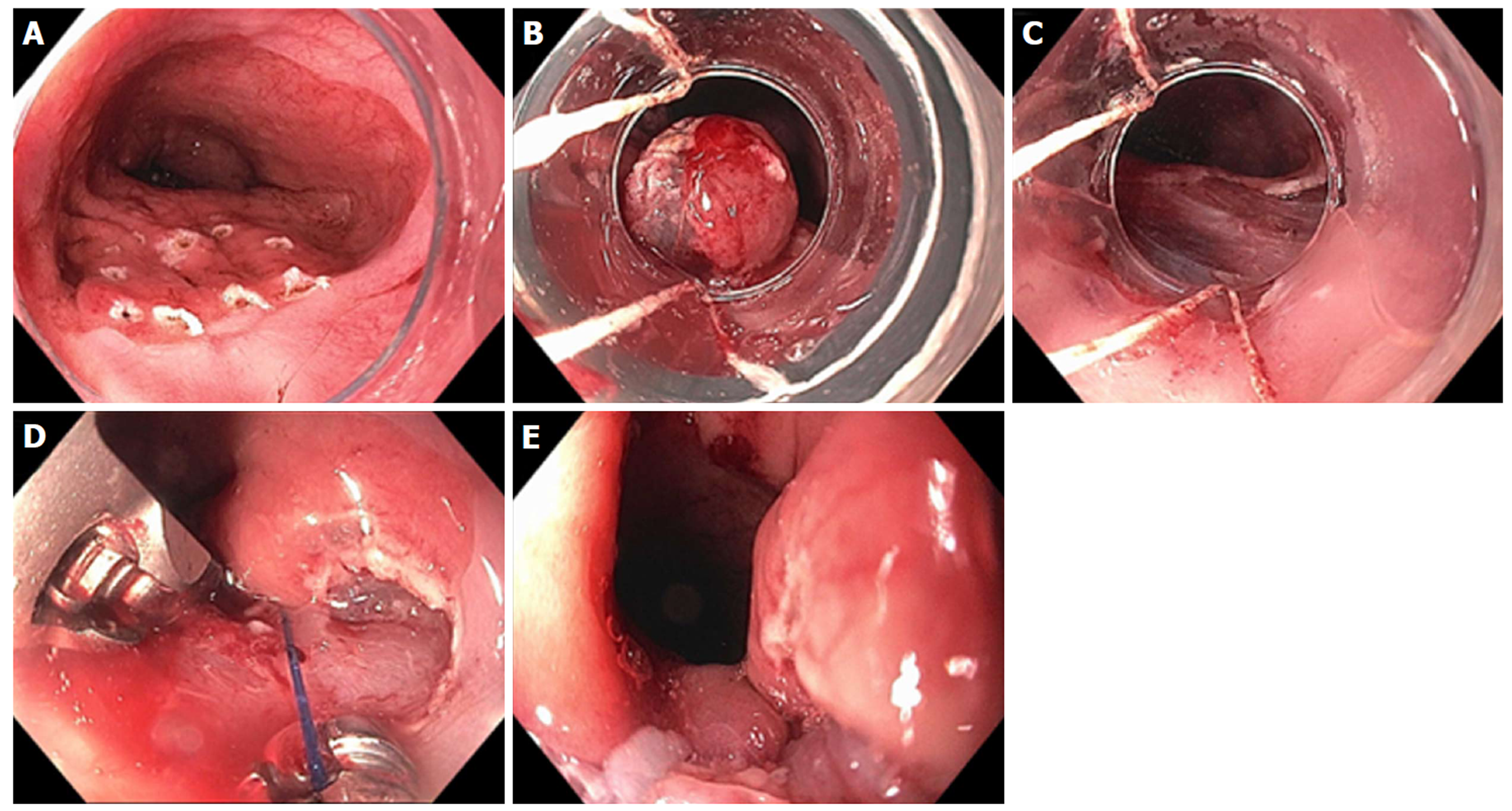
Figure 9 Resection and plication technique for gastroesophageal reflux disease in a patient after gastric by-pass.
A: Endoscopic revision of anastomosis was performed followed by marking area for endoscopic mucosal resection (EMR) at the esophageal gastric junction (EGJ); B: EMR performed using band ligation technique; C: Exposure of muscularis propria accomplished; D: Sutures now deeply placed through muscle layer; E: Post-resection and plication appearance of tightened EGJ.
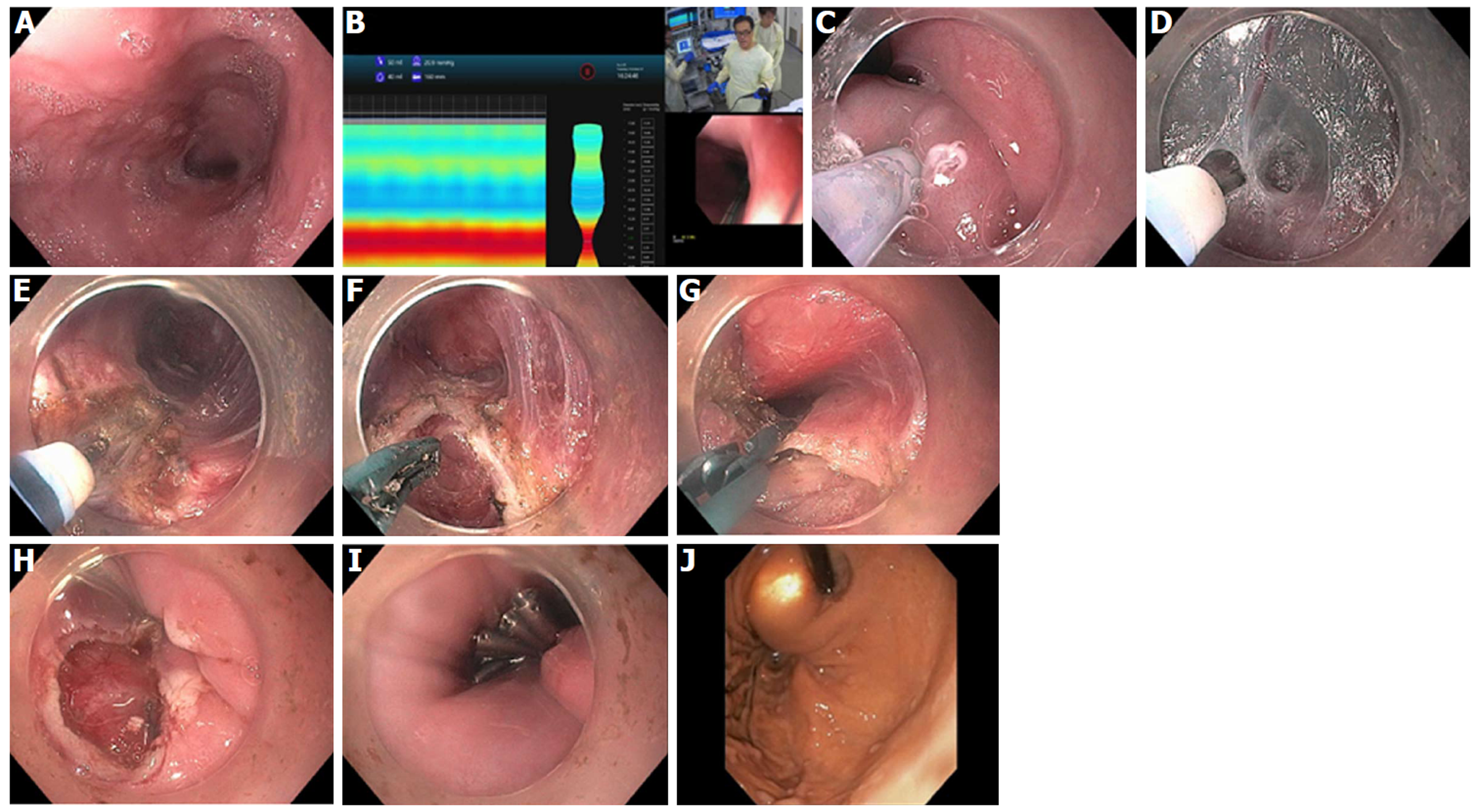
Figure 10 Per-oral endoscopic myotomy procedure on 40-year-old female with type 1 achalasia, s/p pneumatic dilation 20-years prior, now with dysphagia and chest pain/spasms (Eckardt Score 8).
A: Dilated esophageal body; B: Endoscopic functional lumen imaging probe (Endo-Flip) 2.0 showing distensibility of 1.5; C: Initial mucosal incision; D: Submucosal tunnel with coagulation of vessel using Hybrid i-knife; E: Circular myotomy using Hybrid i-knife; F and G: Full thickness myotomy with scissor-type stag beetle (SB) knife; H and I: Closure of mucosotomy using 5 endoscopic clips; J: Thin scope retroflex view of esophageal gastric junction showing light from standard gastroscope within the per-oral endoscopic myotomy tunnel.
Figure 11 Per-oral endoscopic myotomy procedure on 43-year-old female with type 2 achalasia for 25 years, s/p prior failed Heller Myotomy and Botox injection.
A: Abundant submucosal vessels coagulated with stag beetle knife; B: Mucosal incision made in horizontal orientation facilitates closure with endoscopic suturing; C: Double layer suturing, starting with initial bite just left of incision, then middle and right; D: Second running suture from right to left for completion of double layer closure.
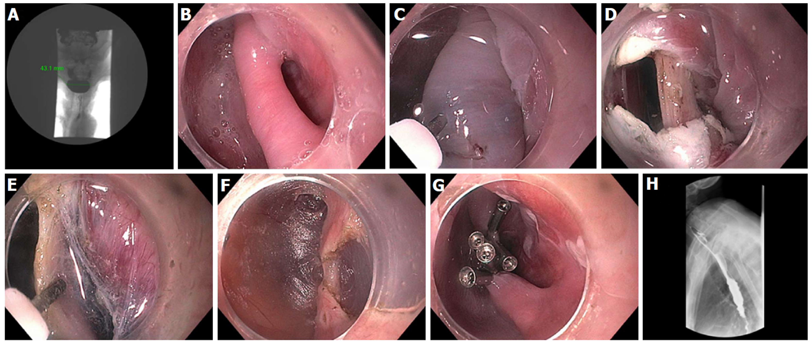
Figure 12 Zenker’s - per-oral endoscopic myotomy procedure in a 91-year-old female with 4-cm Zenker’s diverticulum and dysphagia, including solids, pills, and liquids.
A: Pre- Zenker’s - per-oral endoscopic myotomy procedure (Z-POEM) esophagram showing 4.3 cm Zenker’s; B: Septum identified, with diverticulum on left, and esophageal lumen on right; C: Start of mucosal incision (horizontal) over the septum; D: Mucosal incision completed with exposure of cricopharyngeus muscle (CPM); E: Submucosal tunnel on each side of the CPM; F: Near completion of myotomy; G: Mucosal closure with 5 clips; H: Follow-up esophagram 2 mo post Z-POEM, contrast flows freely, and patient has complete resolution of dysphagia.
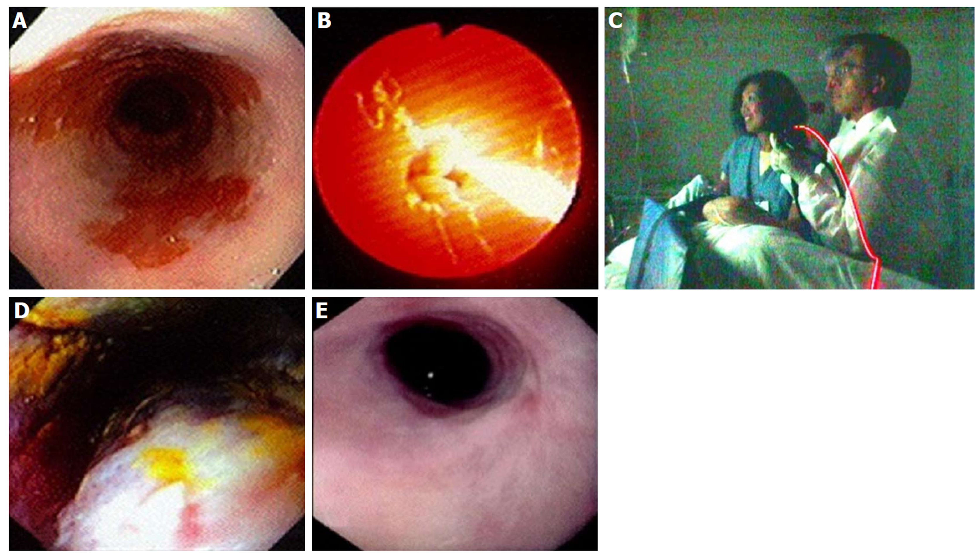
Figure 13 Photodynamic therapy in a patient with Barrett’s esophagus and high grade dysplasia, performed by Dr.
Chang and assistant (who consented to publishing this figure); photo taken in 1997. A: Endoscopic image of 4 cm Barrett’s esophagus (BE) with high grade dysplasia (HGD); B: Photoactivation of photofrin with 630 nm diffuser fiber; C: Room view of diffuser fiber advanced through endoscope; D: Forty-eight hours post photodynamic therapy - endoscopic view of mucosal necrosis; E: Complete eradication of BE and HGD with mild stricture.
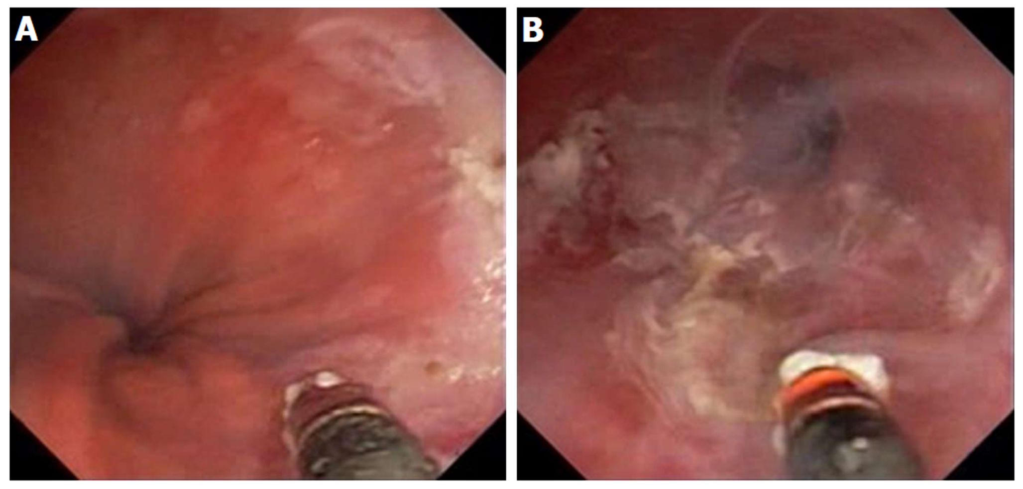
Figure 14 ND:YAG laser for treatment of Barrett’s esophagus with low grade dysplasia.
A: Endoscopy showing sapphire contact probe back-loaded into scope channel; B: Focal ablation of Barrett’s esophagus using ND:YAG contact probe.
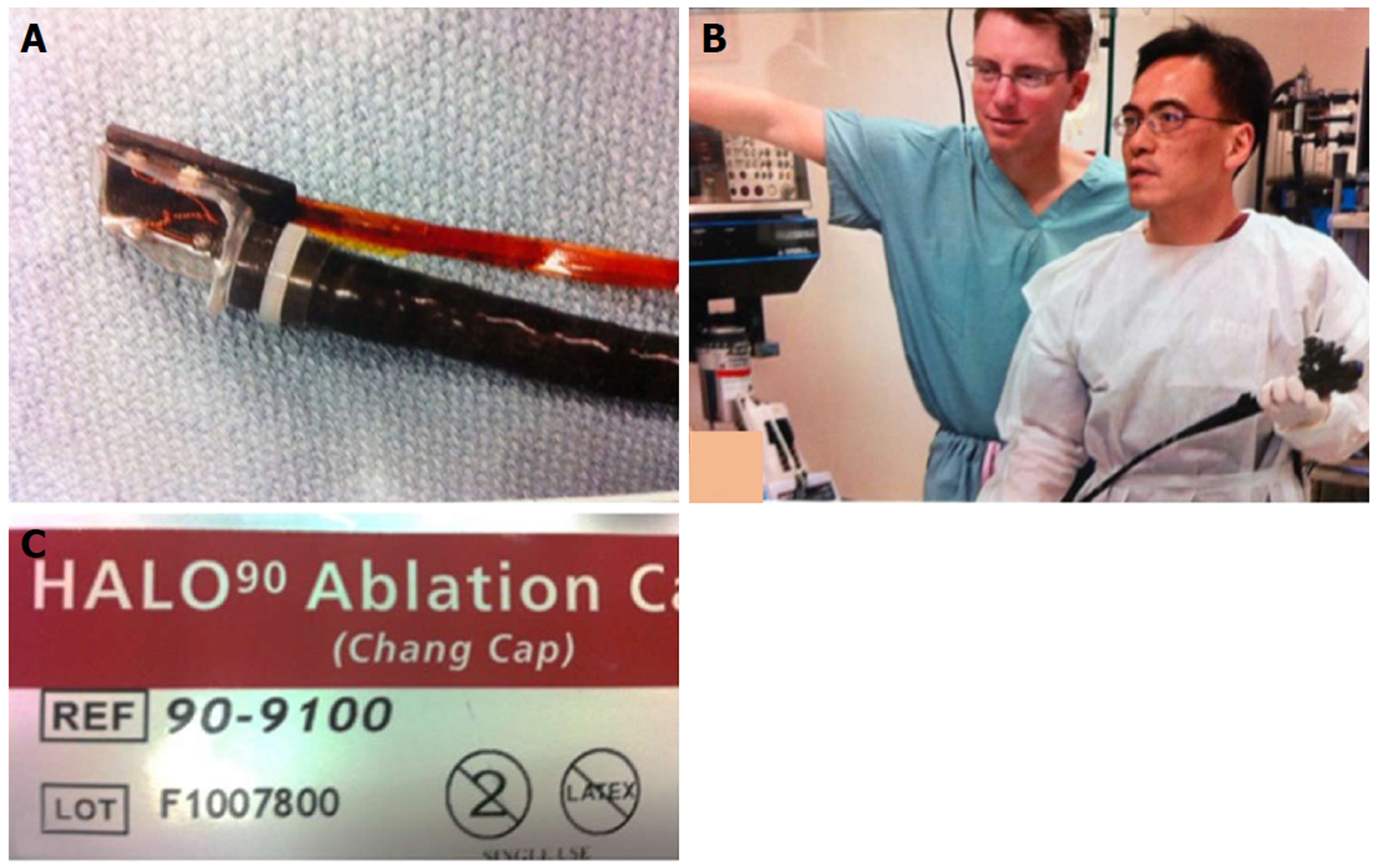
Figure 15 Radiofrequency ablation for Barrett’s using focal device (Halo90), photo taken in 2004.
A: Prototype focal ablation device; B: Dr. Chang working closely with Medical Director of Barrx Medical, Dr. David Utley, to refine technical aspects of focal device; C: Focal ablation device, Halo90, nicknamed “Chang Cap” from 2004 to present. (Dr. Utley gave consent to publish this Figure).
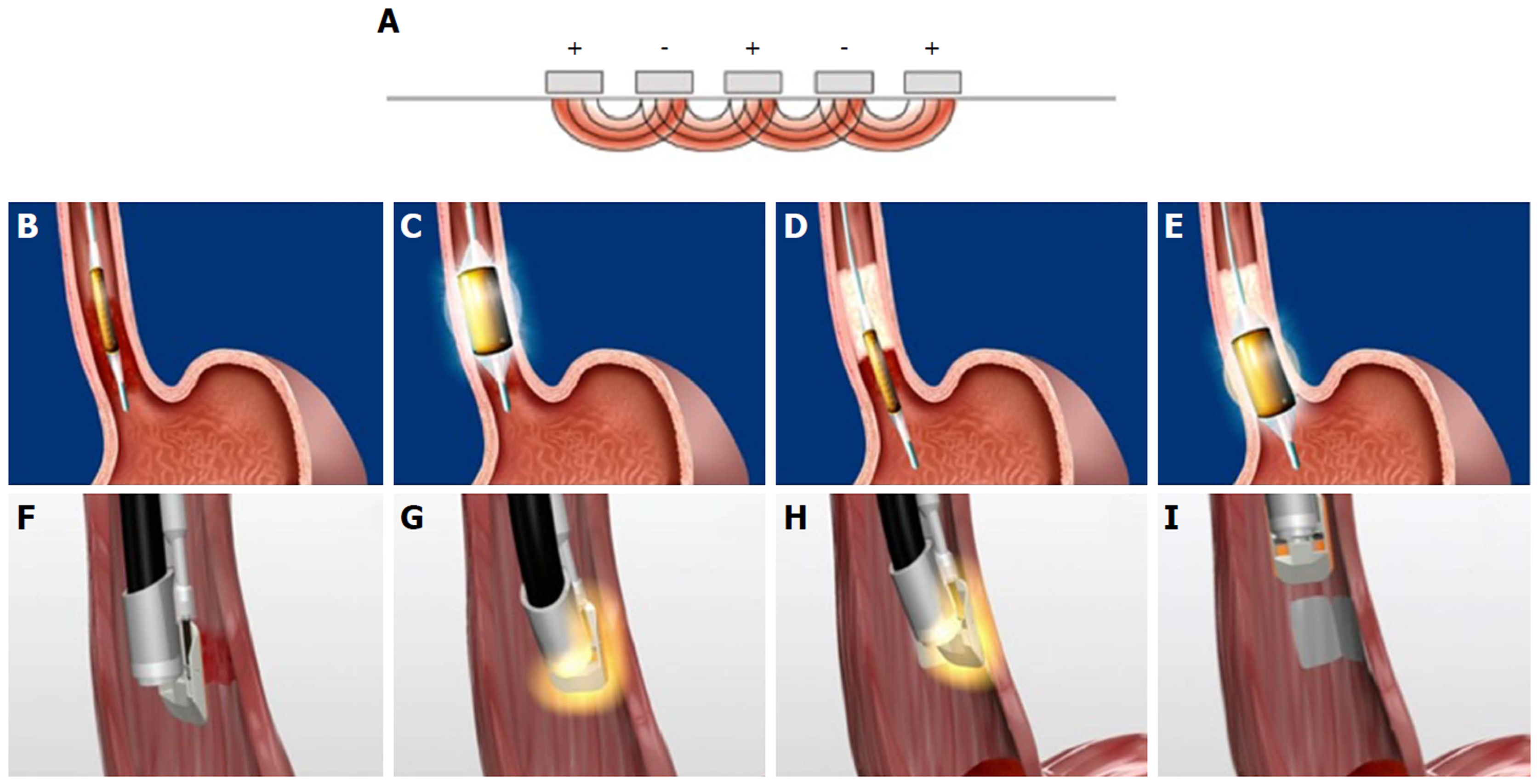
Figure 16 Radiofrequency ablation mechanism and technique.
A: Tightly spaced electrodes (250 µm apart) with pre-set energy and power densities, generator turns off when a pre-determined resistance level in the ablated tissues is reached (mean of 0.3 s); B and C: Circumferential radiofrequency ablation (RFA) delivered by balloon electrode to treat 4 cm segment with single activation; D and E: The catheter is advanced to the next segment with slight overlap; F-I: Focal RFA delivered with Barrx90 device which is secured onto scope tip and endoscopically directed over Barrett’s lesion.
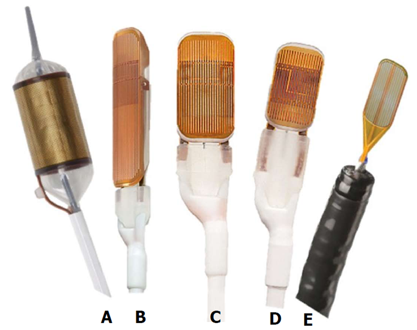
Figure 17 Radiofrequency ablation device “family”.
A: Barrx 360 express, 4 cm self-sizing balloon device; B: Barrx 90 Ultra - 40 mm × 13 mm platform; C: Barrx 90 (Chang Cap) - 20 x 13 mm platform; D: Barrx 60 - 15-10 mm platform; E: Barrx channel catheter - fits through biopsy channel, 15.7 mm × 7.5 mm platform when “wings” expanded.
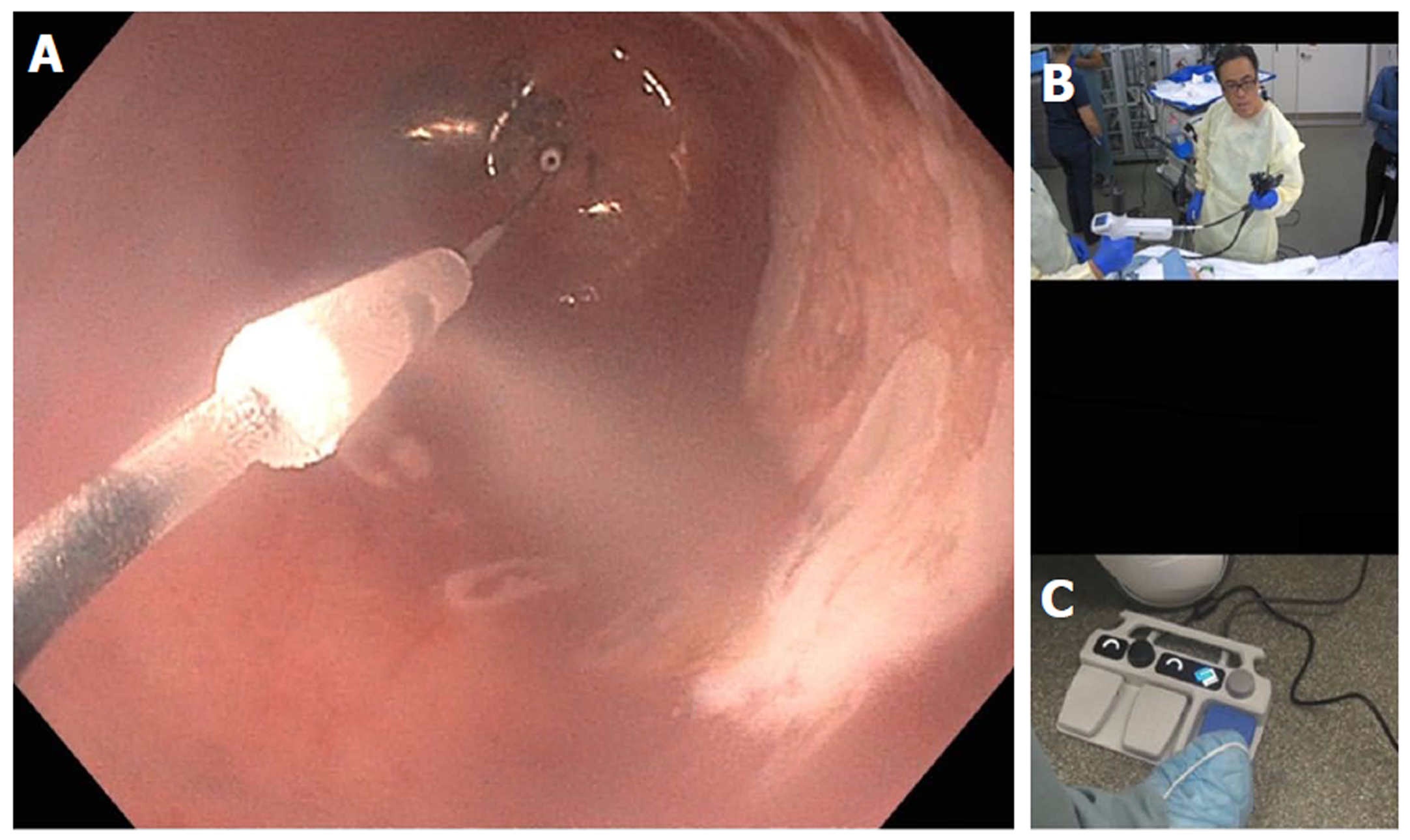
Figure 18 Cryotherapy using nitrous oxide within balloon.
A: Endoscopic view of focal cryoablation of multiple islands of Barrett’s epithelium; marking around the lesion with a snare tip helps with targeting; B: In-room view of hand-held control (by Dr. Chang) with nitrous oxide cartridges; C: New foot pedal console which controls nitrous oxide flow as well as vertical and left-right rotational movement of the spray orifice.
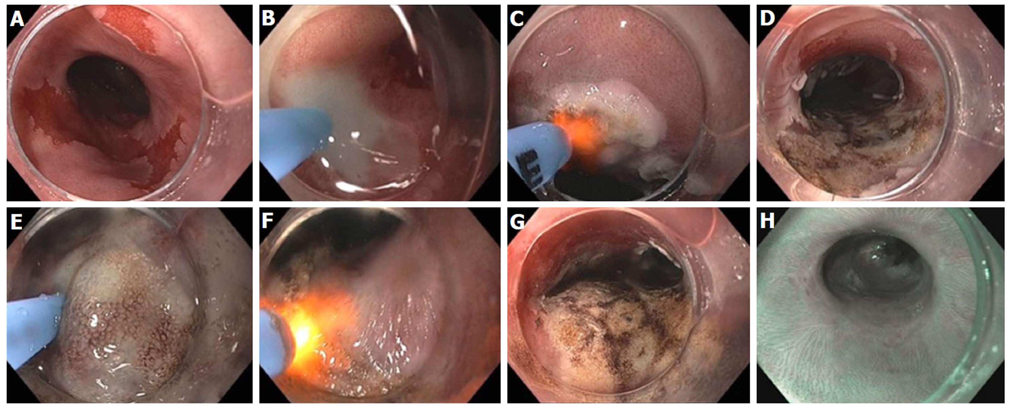
Figure 19 Hybrid argon plasma coagulation to treat residual diffuse, multi-focal Barrett’s after endoscopic submucosal dissection for early esophageal cancer.
A: Endoscopic view of multiple residual Barrett’s islands; B: Needle-free high pressure water jet to create saline cushion in the submucosal space; C: Pass 1 of argon plasma coagulation (APC) ablation with energy settings of Pulsed APC flow rate 0.8 L/min 60 W; endoscopic submucosal dissection (ESD) cap used for visibility, traction and maintaining precise focal distance for even application; D: Completion of Pass 1; E: Repeat water jet into submucosa; F: Pass 2 of APC ablation with energy settings of pulsed APC flow rate 0.8 L/min 40 W; G: Completion of Pass 2 with desired tan colored surface; H: Follow-up endoscopy 6 months post hybrid APC treatment, with biopsy and WATS brushing confirming complete response of intestinal metaplasia.
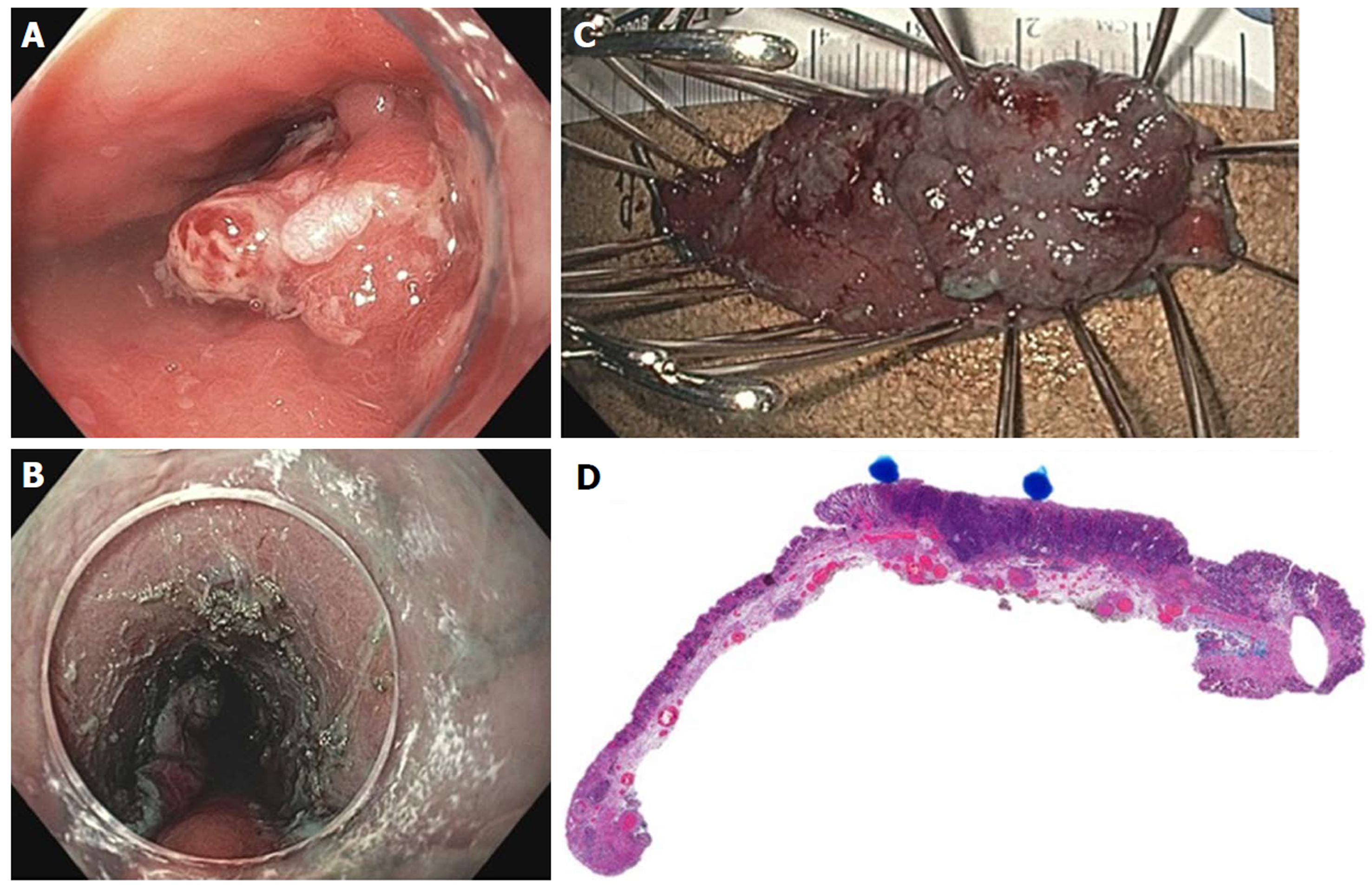
Figure 20 Endoscopic submucosal dissection of early esophageal adenocarcinoma arising from Barrett’s esophagus.
A: Nodular, polypoid (Paris IIa) lesion within long segment Barrett’s esophagus; B: Endoscopic submucosal dissection completed; C: En-bloc resected specimen; D: Histology showing poorly differentiated adenocarcinoma (blue dots), T1b pathologic staging, lateral and deep margins negative (> 300 microns), no lymphovascular invasion.
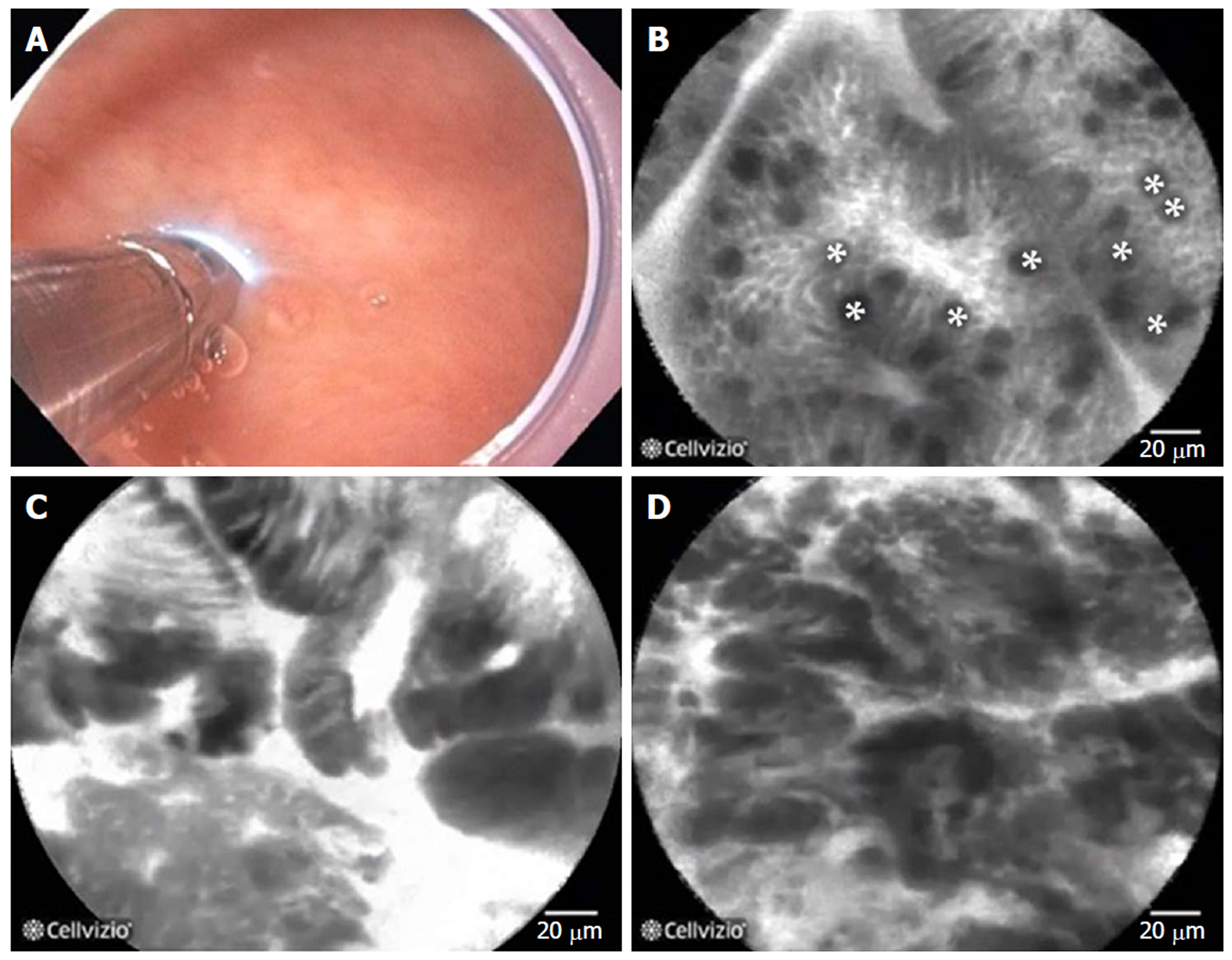
Figure 21 Probe-based confocal laser endomicroscopy in patients with Barrett’s esophagus.
A: the probe is advanced through the biopsy channel, while stabilizing the scope against the mucosa, the probe makes gentle contact with the surface epithelium; B: Probe-based confocal laser endomicroscopy (pCLE) image showing non-dysplastic Barrett’s esophagus (BE). *goblet cells; C: pCLE image showing BE with high grade dysplasia; D: pCLE image showing early adenocarcinoma arising from BE.
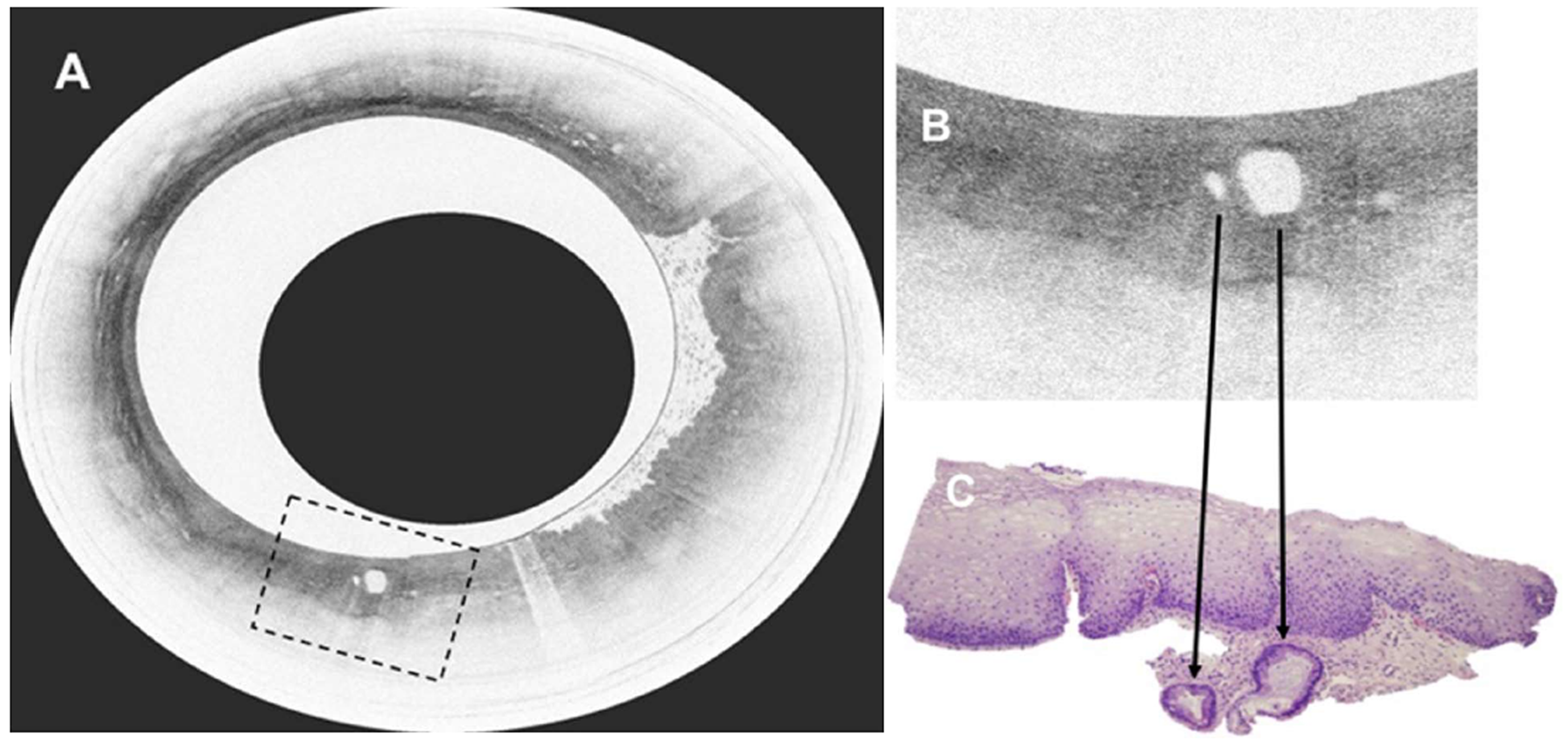
Figure 22 Volumetric laser endomicroscopy in patient with Barrett’s esophagus and high grade dysplasia.
A: Volumetric laser endomicroscopy showing an area of atypical glands covered by normal squamous epithelium; B: Magnification of region of interest (dotted box in image A) showing presence of 2 atypical glands; C: This area underwent endoscopic resection with pathology showing moderately differentiated adenocarcinoma in the background of high grade dysplasia and Barrett’s esophagus. The malignant glandular structures (arrows) were buried beneath squamous epithelium.
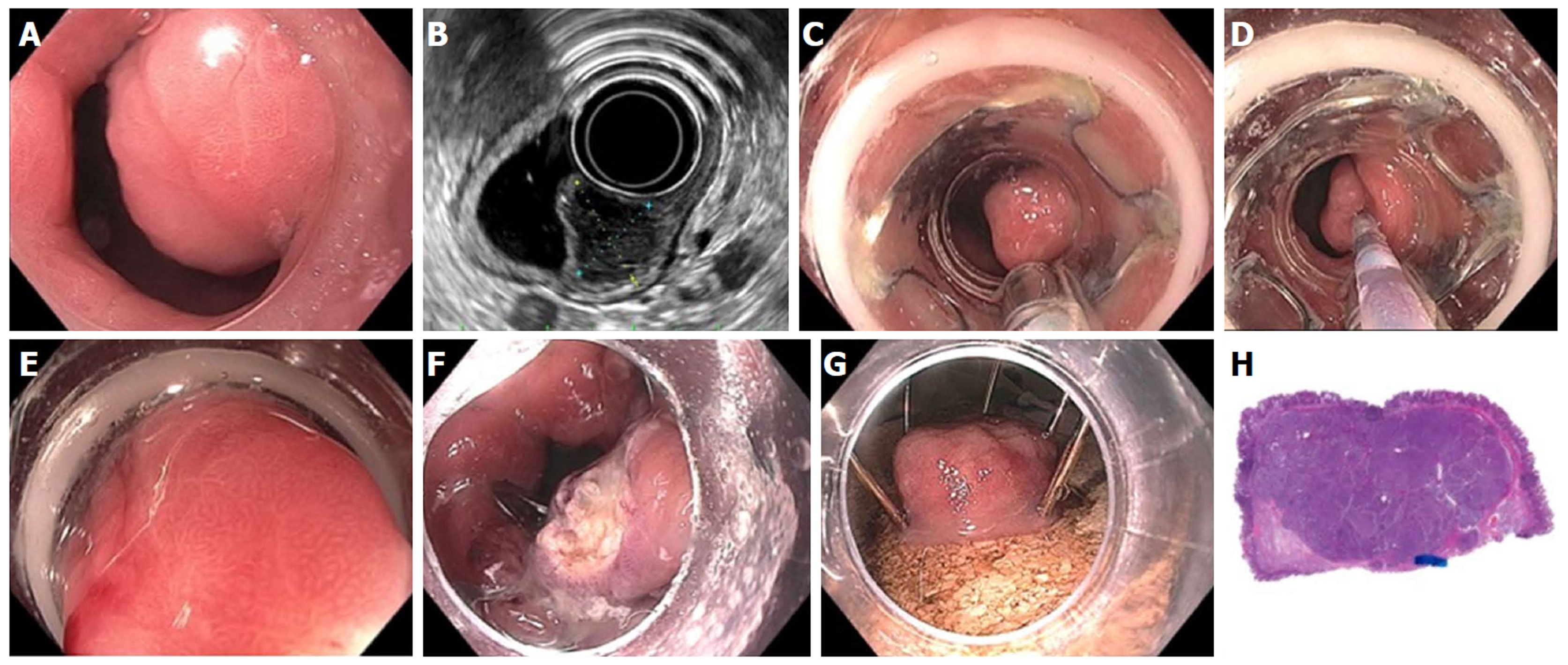
Figure 23 Full thickness resection using FTRD Device for submucosal tumor in the gastric pylorus.
A: One point five centimeters submucosal tumor at the level of pylorus; B: Endoscopic ultrasound showing 1.3 cm × 1.1 cm submucosal tumor concerning for neuroendocrine tumor; C: Lesion viewed through double channel therapeutic scope with 21-mm transparent cap; D: Helical retractor was used to secure the lesion and pull it into the cap; E: Entire lesion is now within the cap; F: The entire wall was captured in the large clip and resection was completed above the closed clip; G: Lesion resected en bloc; H: Histologic specimen showing complete specimen with negative deep and lateral margins.
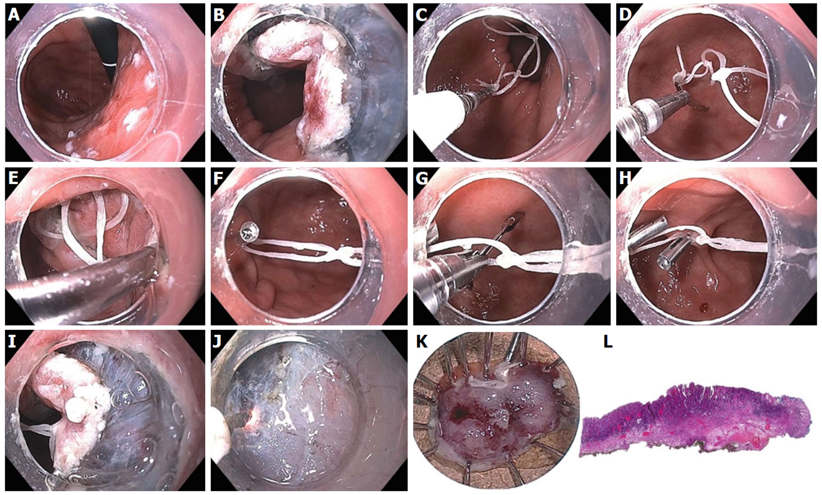
Figure 24 Endoscopic submucosal dissection of 15-mm IIa+c intramucosal carcinoma of stomach along lesser curve body using multi-loop technique.
A: The lesion is marked using spot coagulation; B: Circumferential incision is performed using the i-knife, however the angle of approach on the proximal side is difficult for submucosal entry and dissection; C: Three loops are created using dental floss, captured with a clip passed through the biopsy channel (no need for scope removal or additional equipment); D: The clip is opened (the string can be pre-tied to one leg of the clip) and positioned to grasp the proximal edge of the specimen; E: The 1st clip is released, anchoring the string to the specimen; F: A 2nd clip is used to catch the distal loop and anchor to opposite wall of stomach; G: If necessary, a 3rd clip can be used to grasp the middle loop; H: This can be helpful to further tighten or re-direct the traction angle; I: the submucosal space is much easier to enter with multi-loop traction; J: submucosal dissection in the antegrade approach is greatly facilitated; K: The specimen is resected en bloc; L: Histology confirmed a well differentiated grade 1 adenocarcinoma with invasion to the muscularis mucosa with negative deep and lateral margins, no lymphovascular invasion.
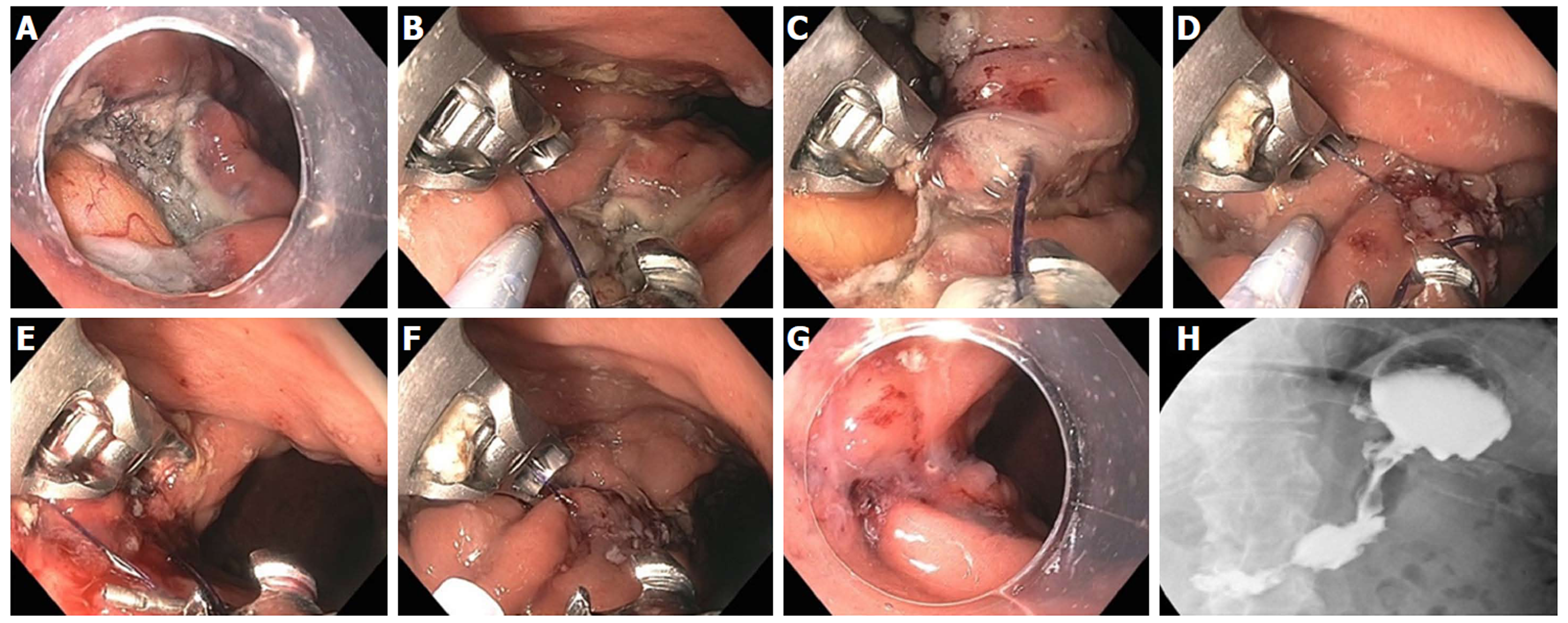
Figure 25 Large gastric defect after full thickness resection of neuroendocrine tumor closed with endoscopic suturing.
A: Four-centimeter full thickness wound in posterior body of stomach, omental fat seen at base of defect; B: First suture - use helical tissue retractor to grab left edge of distal defect; C: After taking first bite on distal left (needle going from mucosa to serosa), second bite on distal right (needle going from serosa to mucosa); D: Approximately 8 bites are taken, alternating from left to right, with the last bite having the needle from mucosa-serosa-mucosa in single throw; E: First continuous running suture completed and needle anchor released for tightening and suture release; F: Second row of running suture placed for double reinforcement; G: Double suture closure completed; H: Contrast study shows luminal narrowing with no leak.
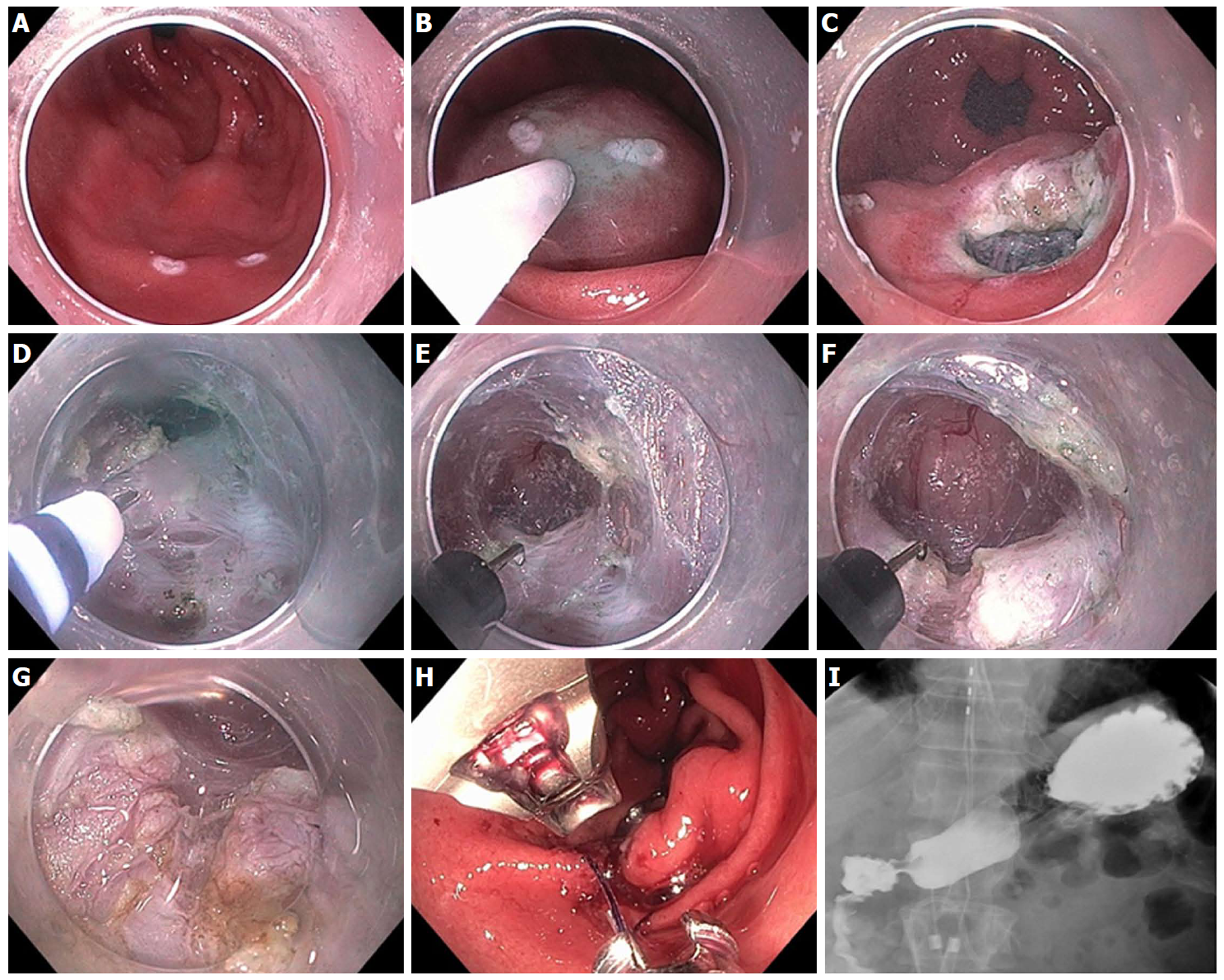
Figure 26 Gastric per-oral endoscopic pyloromyotomy in a patient with severe gastroparesis.
A: Markings made for mucosal incision on the antrum greater curve, 4-5 cm proximal to the pylorus; B: Submucosal injection; C: Initial mucosal incision; D: Submucosal tunnel extended with i-knife until pylorus muscle is identified; E: The hook knife is then used to carefully cut the pylorus muscle; F: Myotomy of the pylorus; G: The myotomy is extended proximally for approximately 2 cm along the antrum; H: Closure of the mucosotomy is accomplished with Overstitch suturing device; I: Upper gastrointestinal contrast X-ray study shows no leak, with free flow of contrast through the pylorus.
Figure 27 Endoscopic sleeve gastroplasty plus mucosal ablation and suturing of the esophageal gastric junction in a 45-year-old female with super morbid obesity, gastroparesis and gastroesophageal reflux disease.
Her body mass index was 51 (327 lb) and she declined bariatric surgery. A: Markings created along anterior and posterior gastric wall to guide suture placement; B: First suture placed by taking bites at anterior, greater curve, posterior wall × 2; C: Total of 8 running sutures placed to complete the “sleeve”; D: At the very proximal aspect of the sleeve, a final suture is placed in a purse-string fashion around an 8 mm balloon to prevent complete closure; E: Endoscopic appearance within the completed sleeve; F: Endoscopic appearance of the proximal “pouch” which filled up with approximately 60 mL of water; G: Mucosal ablation and suturing of the esophageal gastric junction (MASE) procedure was performed as well, using 3 additional sutures, to treat her gastroesophageal reflux disease; H: UGI X-ray with contrast 1 d post endoscopic sleeve gastroplasty and MASE shows contrast filling the small gastric pouch with little to no passage through the sleeve at 1 h.
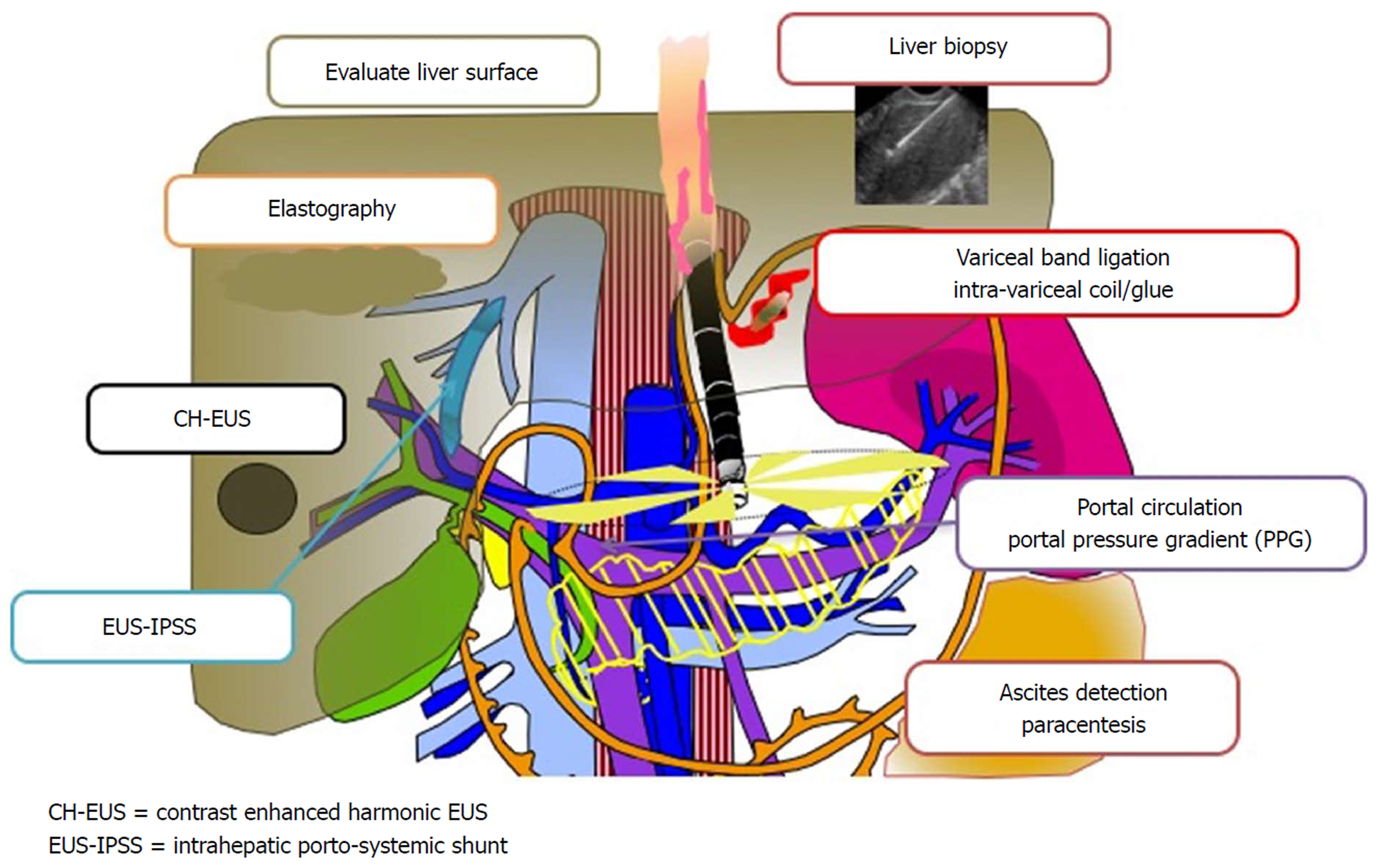
Figure 28 A promising new paradigm “Endo-Hepatology” intersects and integrates endoscopy in the diagnosis and treatment of liver disease.
This includes: evaluation of the liver surface [by endoscopic ultrasound (EUS)], elastography to determine liver stiffness and fibrosis, contrast enhanced harmonic EUS to detect focal lesions, EUS-guided intrahepatic porto-systemic shunt, EUS-guided liver biopsy, endoscopic variceal band ligation and intra-variceal injection with glue +/- coil (by EUS), evaluation of the portal circulation and EUS-guided portosystemic pressure gradient, and detection of ascites with EUS-guided paracentesis. EUS: Endoscopic ultrasound; PPG: Portosystemic pressure gradient; IPSS: Intrahepatic porto-systemic shunt.
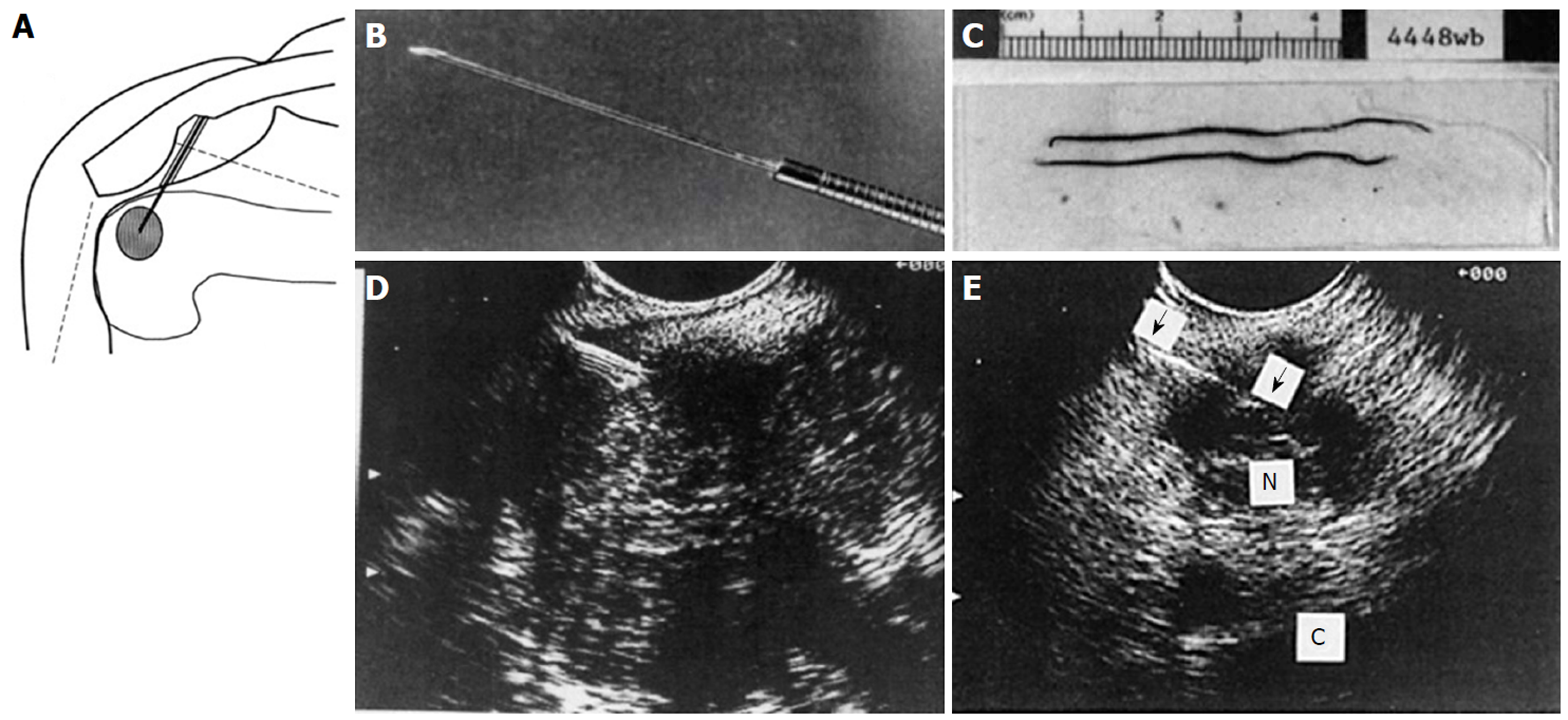
Figure 29 Endoscopic ultrasound guided fine needle aspiration initial series of 38 patients reported in 1994.
A: Diagram of endoscopic ultrasound (EUS) guided fine needle aspiration (FNA) created on first generation Apple Macintosh computer; B: Black and white photo of prototype 23G 4-cm FNA needle attached to Teflon tubing; C: Photo of needle specimen, much of which was probably blood clot; D: Early linear array EUS image showing needle coming from left side, as established by ultrasound convention at the time, into a pancreatic tumor; E: EUS image of FNA needle into a 1.5-cm celiac lymph node. (Reprinted with permission from reference 173).
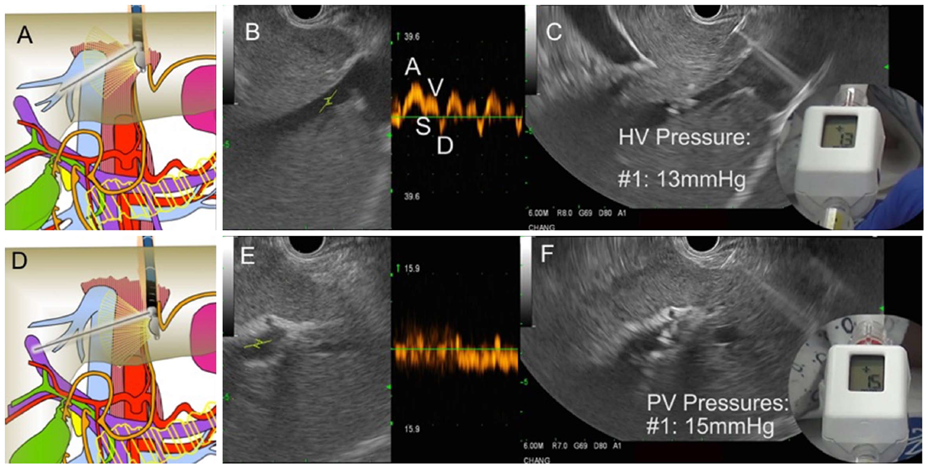
Figure 30 Endoscopic aultrasound guided portosystemic pressure gradient measurement in a patient with suspected cirrhosis.
A: Diagram showing fine needle aspiration (FNA) needle within the middle hepatic vein; B: Endoscopic ultrasound (EUS) image of middle hepatic vein with Doppler wave form demonstrating 4 phases (ASVD); C: 25G needle placed directly through liver parenchyma into the middle hepatic vein; compact hand-held manometer showing a pressure of 13 mmHg; D: Diagram FNA needle within the left portal vein; E: EUS image of left portal vein (umbilical portion); typical Doppler waveform showing venous hum; F: 25G needle placed directly through liver parenchyma into the left portal vein; compact hand-held manometer showing a pressure of 15 mmHg. Thus, the EUS-portosystemic pressure gradient measurement is 2 mmHg, which is within normal range.
- Citation: Chang KJ. Endoscopic foregut surgery and interventions: The future is now. The state-of-the-art and my personal journey. World J Gastroenterol 2019; 25(1): 1-41
- URL: https://www.wjgnet.com/1007-9327/full/v25/i1/1.htm
- DOI: https://dx.doi.org/10.3748/wjg.v25.i1.1


