Copyright
©2009 The WJG Press and Baishideng.
World J Gastroenterol. Sep 21, 2009; 15(35): 4402-4409
Published online Sep 21, 2009. doi: 10.3748/wjg.15.4402
Published online Sep 21, 2009. doi: 10.3748/wjg.15.4402
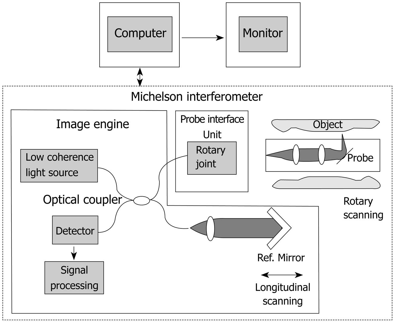
Figure 1 Schema of the OCT system (Light Lab Imaging, Boston, USA, and HOYA, Tokyo, Japan) used in the present study.
Near infrared light is generated from the light source, and then is split evenly. One beam is directed to the tissue sample and the other to a reference mirror. The light is reflected from both the sample and mirror. The reflected light beams are recombined in a beam splitter.
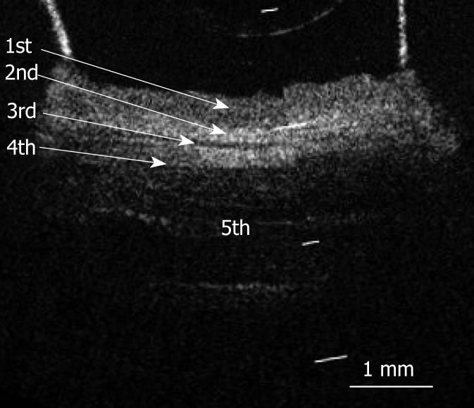
Figure 2 OCT image of a fresh pig esophageal wall specimen.
OCT image of the esophageal wall delineated a five-layered morphology (arrows) consisting of a relatively less reflective layer (the first layer), a more reflective layer (the second layer), a less reflective layer (the third layer), a more reflective layer (the fourth layer), and a less reflective layer (the fifth layer). The white bar represents 1 mm.
Figure 3 OCT image and corresponding histological sections of esophageal wall specimen injected with cyanoacrylate adhesive into the first layer.
A: OCT image of the esophageal wall specimen injected with cyanoacrylate adhesive into the first layer (relatively less reflective layer). The injection location of cyanoacrylate adhesives into the first layer is clearly recognized. B: Corresponding histological section. The cyanoacrylate adhesive is observed in the stratified squamous epithelium (HE, original magnification × 4). C: Corresponding histological section (EM, original magnification × 4). The white and black bars represent 1 mm. EP: Stratified squamous epithelium; LP: Lamina propria; MM: Muscularis mucosa; SM: Submucosa; MP: Muscularis propria; AD: Adventitious tissue.
Figure 4 OCT image and corresponding histological sections of esophageal wall specimen injected with cyanoacrylate adhesive into the second layer.
A: OCT image of the esophageal wall specimen injected with cyanoacrylate adhesive into the second layer (more reflective layer). The injection location of cyanoacrylate adhesive into the 2nd layer is clearly recognized. B: Corresponding histological section. The cyanoacrylate adhesive is observed in the lamina propria (HE, original magnification × 4). C: Corresponding histological section (EM, original magnification × 4). The white and black bars represent 1 mm.
Figure 5 OCT image and corresponding histological sections of esophageal wall specimen injected with cyanoacrylate adhesive into the third layer.
A: OCT image of esophageal wall injected with cyanoacrylate adhesive into the third layer (less reflective layer). The injection location of cyanoacrylate adhesive into the third layer is clearly recognized. B: Corresponding histological section. The cyanoacrylate adhesive is observed in the muscularis mucosa (HE, original magnification × 4). C: Corresponding histological section (EM, original magnification × 4). The white and black bars represent 1 mm.
Figure 6 OCT image and corresponding histological sections of esophageal wall specimen injected with cyanoacrylate adhesive into the fourth layer.
A: OCT image of esophageal wall specimen injected with cyanoacrylate adhesive into the fourth layer (more reflective layer). The injection location of cyanoacrylate adhesive into the fourth layer is clearly recognized. B: Corresponding histological section. The cyanoacrylate adhesive is observed in submucosa (HE, original magnification × 4). C: Corresponding histological section (EM, original magnification × 4). The white and black bars represent 1 mm.
Figure 7 OCT image and corresponding histological sections of esophageal wall specimen injected with cyanoacrylate adhesive into the fifth layer.
A: OCT image of esophageal wall specimen injected with cyanoacrylate adhesive into the fifth layer (less reflective layer). The large white arrow indicates the injection location for cyanoacrylate adhesive. B: Corresponding histological section. The cyanoacrylate adhesive is observed in the muscularis propria (HE, original magnification × 4). C: Corresponding histological section (EM, original magnification × 4). The white and black bars represent 1 mm.
Figure 8 OCT image and corresponding histological sections of esophageal wall specimen with a thin nylon suture in the first layer.
A: OCT image of esophageal wall specimen with a thin nylon suture in the first layer (relatively less reflective layer). The marker of the thin nylon suture (large white arrow) is recognized in the 1st layer. B: Corresponding histological section. The fragment of nylon suture is observed in the stratified squamous epithelium. (HE, original magnification × 4). C: Corresponding histological section (EM, original magnification × 4). The white and black bars represent 1 mm.
Figure 9 OCT image and corresponding histological sections of esophageal wall specimen with a thin nylon suture in the second layer.
A: OCT image of esophageal wall specimen with a thin nylon suture in the second layer (more reflective layer). The marker of the thin nylon suture (large white arrow) is recognized in the second layer. B: Corresponding histological section. The fragment of thin nylon suture is observed in the lamina propria. (HE, original magnification × 4). C: Corresponding histological section (EM, original magnification × 4). The white and black bars represent 1 mm.
Figure 10 OCT image and corresponding histological sections of esophageal wall specimen with a thin nylon suture in the third layer.
A: OCT image of esophageal wall specimen with a thin nylon suture in the third layer (more reflective layer). The marker of thin nylon suture (large white arrow) is recognized in the third layer. B: Corresponding histological section. The fragment of thin nylon suture is observed in the muscularis mucosa. (HE, original magnification × 4). C: Corresponding histological section (EM, original magnification × 4). The white and black bars represent 1 mm.
Figure 11 OCT image and corresponding histological sections of esophageal wall specimen with a thin nylon suture in the fourth layer.
A: OCT image of esophageal wall specimen with a thin nylon suture in the fourth layer (more reflective layer). The marker of thin nylon suture (large white arrow) is recognized in the fourth layer. B: Corresponding histological section. The fragment of nylon suture is observed in the submucosa. (HE, original magnification × 4). C: Corresponding histological section (EM, original magnification × 4). The white and black bars represent 1 mm.
Figure 12 OCT image and corresponding histological sections of esophageal wall specimen with a thin nylon suture in the fifth layer.
A: OCT image of esophageal wall specimen with a thin nylon suture in the fifth layer (more reflective layer). The marker of thin nylon suture (indicated within white circle) is recognized in the fifth layer. B: Corresponding histological section. The fragment of nylon suture is observed in the muscularis propria. (HE, original magnification × 4). C: Corresponding histological section (EM, original magnification × 4). The white and black bars represent 1 mm.
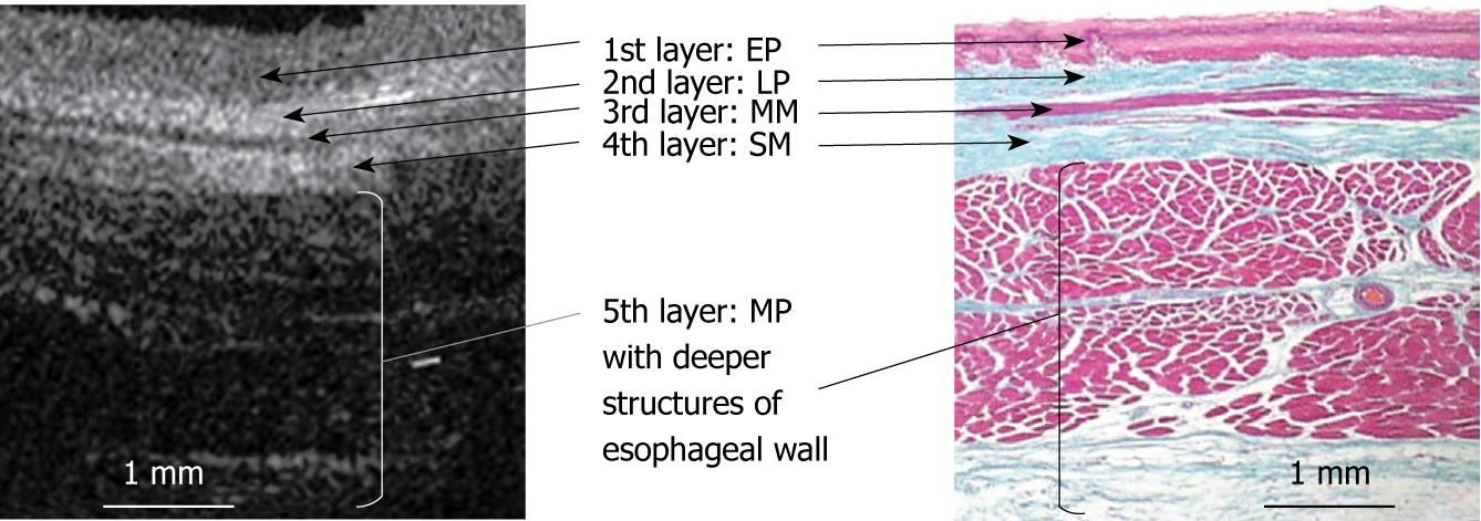
Figure 13 A schema of the correspondence between the OCT image of normal esophagus and histology.
The OCT image of normal esophageal wall delineates a five-layered morphology, consisting of relatively less reflective stratified squamous epithelium (the first layer), more reflective lamina propria (the second layer), less reflective muscularis mucosa (the third layer), more reflective submucosa (the fourth layer), and less reflective muscularis propria with deeper structures of esophageal wall (the fifth layer). (EM, original magnification × 4). The white and black bars represent 1 mm.
- Citation: Yokosawa S, Koike T, Kitagawa Y, Hatta W, Uno K, Abe Y, Iijima K, Imatani A, Ohara S, Shimosegawa T. Identification of the layered morphology of the esophageal wall by optical coherence tomography. World J Gastroenterol 2009; 15(35): 4402-4409
- URL: https://www.wjgnet.com/1007-9327/full/v15/i35/4402.htm
- DOI: https://dx.doi.org/10.3748/wjg.15.4402


