Copyright
©The Author(s) 2020.
Artif Intell Med Imaging. Aug 28, 2020; 1(2): 78-86
Published online Aug 28, 2020. doi: 10.35711/aimi.v1.i2.78
Published online Aug 28, 2020. doi: 10.35711/aimi.v1.i2.78
Figure 1 Main flowchart of optical molecular tomography.
3D: Three-dimensional; MRI: Magnetic resonance imaging; OMT: Optical molecular tomography; XCT: X-ray computed tomography.
Figure 2 Reconstruction results with a priori information.
A and B: The axial and sagittal views of single photon emission computed tomography/computed tomography imaging, and an implanted light source is inserted into a mouse; C: The axial-view result of the reconstructed source. These images are reproduced from[47].
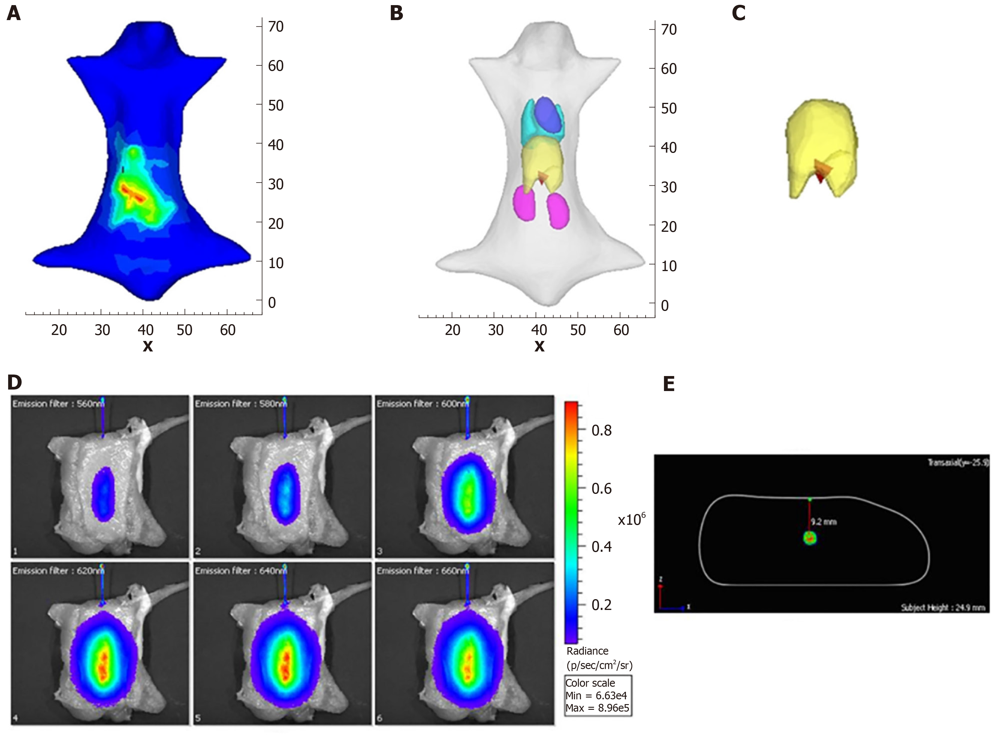
Figure 3 Reconstruction results with posteriori information.
A: The luminescence distribution in the body; B and C: The three-dimensional results and the results of the local enlarged image in the local area of the liver; C: The images of the capillary acquired using six filters; D, E: The trans-axial multispectral-Cerenkov luminescence tomography reconstructed image of the capillary filled with 32P-ATP at a 9 mm depth. A and B are reproduced from[67], while C and D are reproduced from[62].
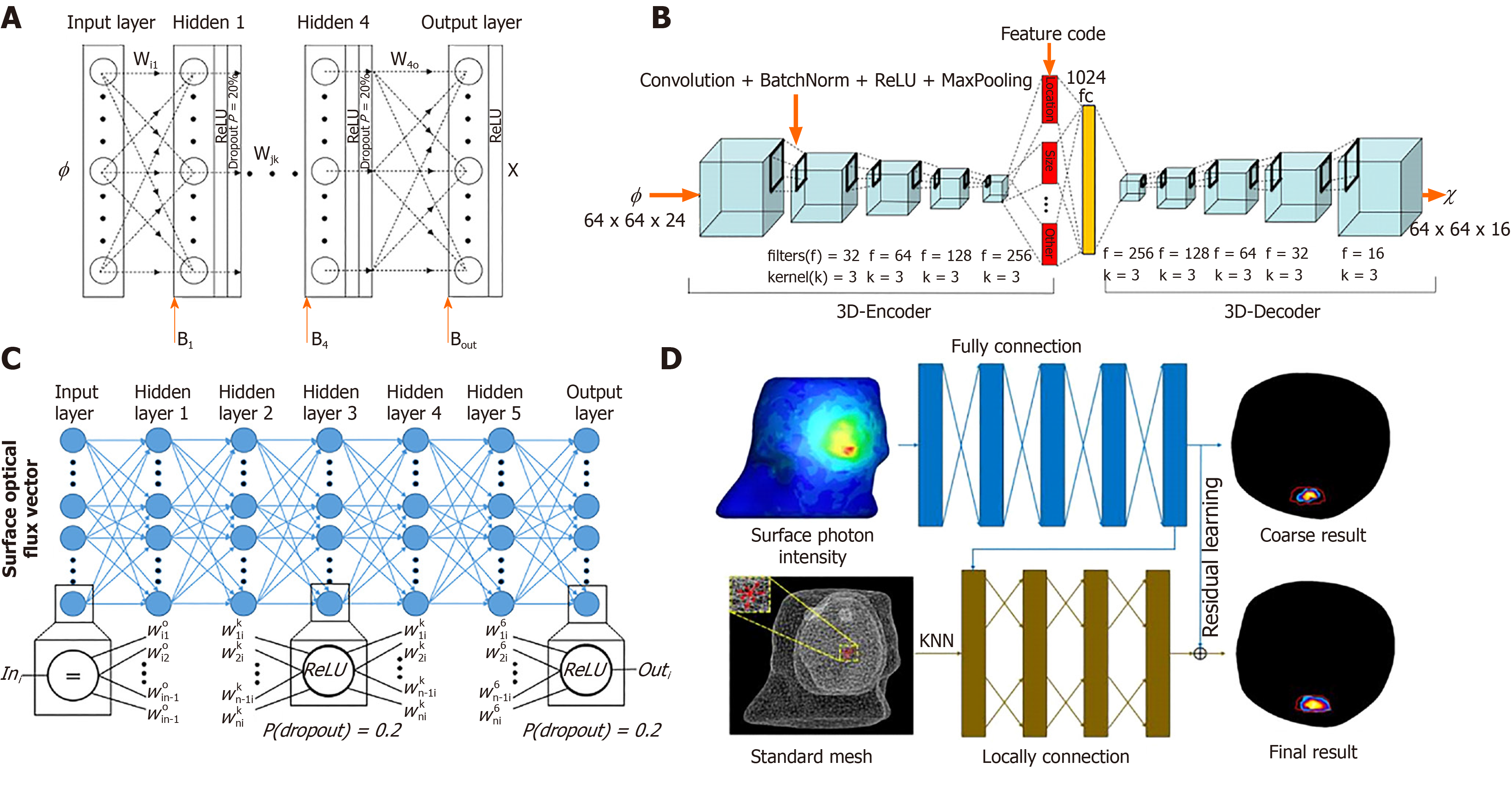
Figure 4 Structure of the networks used in optical molecular tomography reconstruction.
A: Multilayer perceptron-based bioluminescence tomography reconstruction network reproduced from[72]; B: Convolutional neural network-recurrent neural network-based fluorescence molecular tomography (FMT) reconstruction framework reproduced from[74]; C: Multilayer fully-connected neural network based on Cerenkov luminescence tomography reproduced from[75]; D: K-nearest neighbor-based locally connected network based on FMT reproduced from[76].
- Citation: Cao X, Li K, Xu XL, Deneen KMV, Geng GH, Chen XL. Development of tomographic reconstruction for three-dimensional optical imaging: From the inversion of light propagation to artificial intelligence. Artif Intell Med Imaging 2020; 1(2): 78-86
- URL: https://www.wjgnet.com/2644-3260/full/v1/i2/78.htm
- DOI: https://dx.doi.org/10.35711/aimi.v1.i2.78


