©The Author(s) 2020.
World J Transplant. May 29, 2020; 10(5): 129-137
Published online May 29, 2020. doi: 10.5500/wjt.v10.i5.129
Published online May 29, 2020. doi: 10.5500/wjt.v10.i5.129
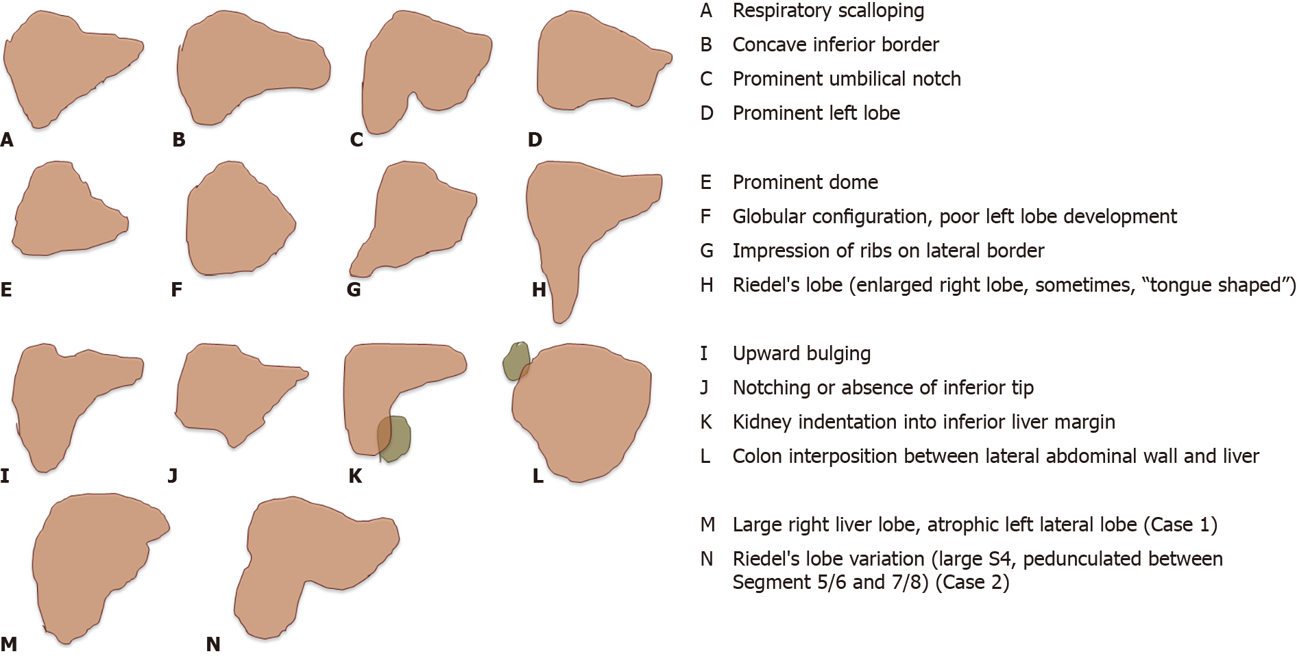
Figure 1 Schematic overview of anatomical liver variations, adapted from Sabih et al[6].
H and N show different anatomical variations with Riedel’s lobes as previously described with a tongue like shape.
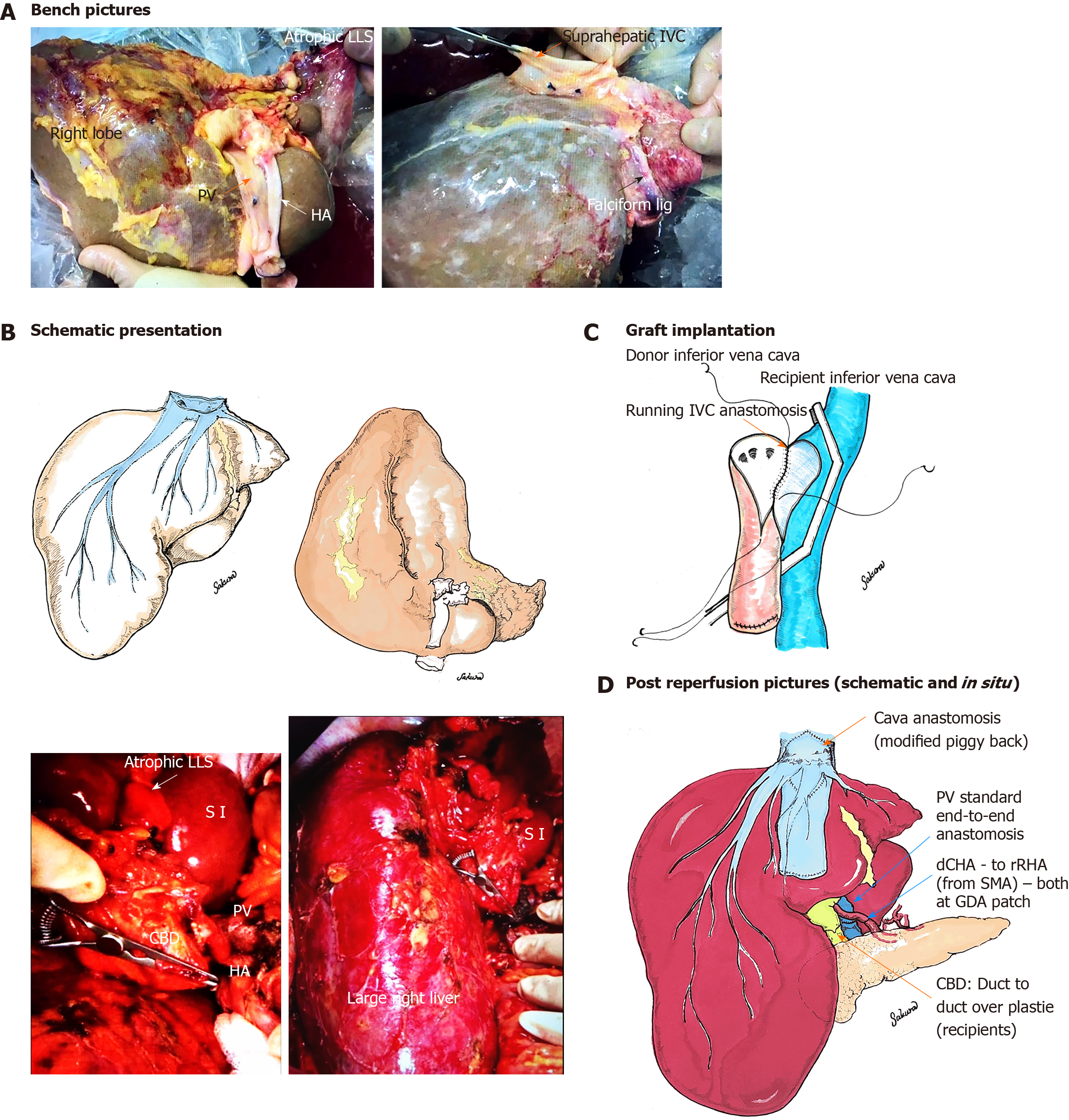
Figure 2 Schematic overview of donor liver with Riedel’s lobe (Case 1): Bench pictures.
A: Demonstrate atrophic left lateral segment with limited tissue on the left side of the falciform ligament and large right liver Riedel’s lobe with maintained liver vascularity including normal supra-hepatic inferior vena cava, portal vein and donor hepatic artery, donor had previous cholecystectomy; Schematic presentation of liver; B: Modified Piggy-Back anastomosis (side-to-side); C: With creation of a larger orifice compared to simple side-to-side cavo-cavostomy, Reperfusion pictures, schematic and in vivo; D: Modified side to side piggyback implantation with large teardrop incision of both donor and recipient inferior vena cava, reperfusion through portal vein first (end-to-end reconstruction, standard), end-to-end anastomosis between donor common hepatic artery and right common hepatic artery both at gastroduodenal artery patch. LLS: Left lateral segment; HA: Hepatic artery; PV: Portal vein; IVC: Inferior vena cave; CHA: Common hepatic artery; RHA: Right hepatic artery; SMA: Supra-mesenteric artery; GDA: Gastroduodenal artery; CBD: Common bile duct.
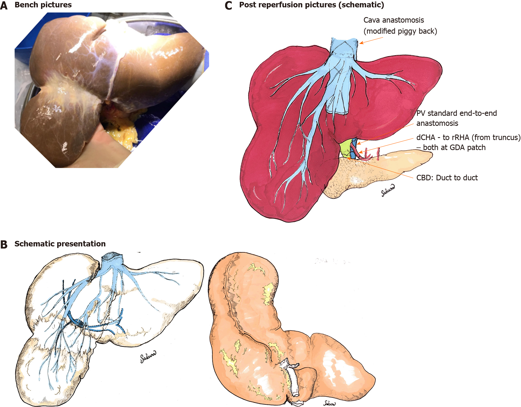
Figure 3 Schematic overview of donor liver with Riedel’s lobe (Case 2): Bench picture.
A: Schematic presentation of the liver; B: With large segmental separation of S6/7 and 5/8, a special variation of a Riedel’s lobe and the implantation technique; C: The implantation was performed with a side to side piggy back technique in a routine way with longitudinal incision of the donor and recipient inferior vena cava. This was in contrast to the first case. PV: Portal vein; CHA: Common hepatic artery; RHA: Right hepatic artery; GDA: Gastroduodenal artery; CBD: Common bile duct.
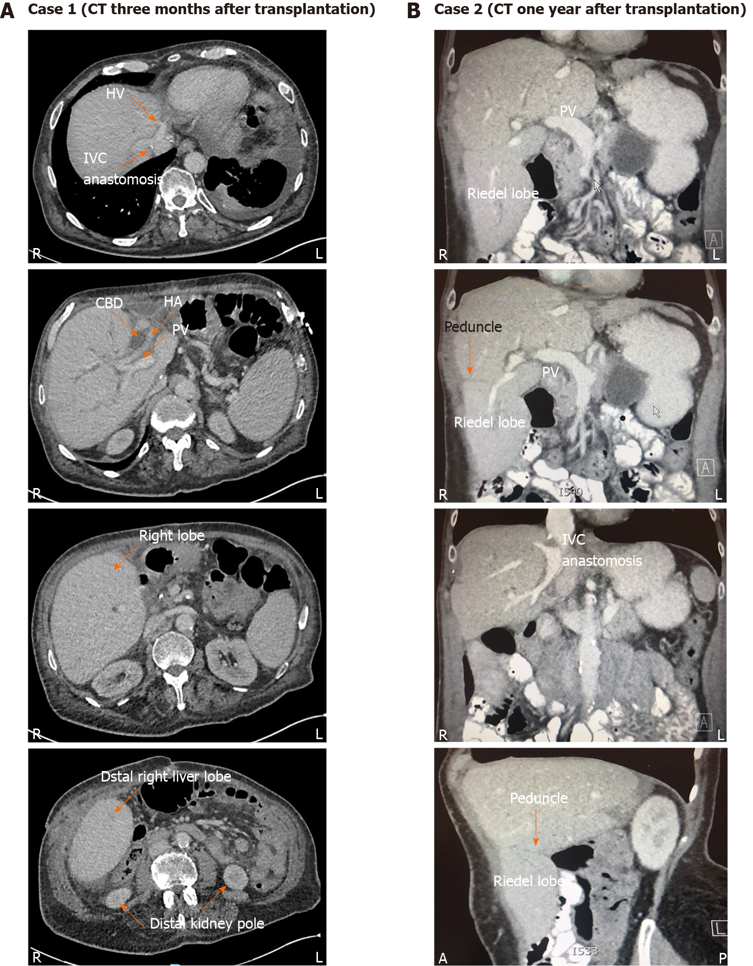
Figure 4 Cross-sectional imaging after liver transplantation.
Case 1 (computer tomography scan, performed 3 mo after liver transplantation, local hospital admission for diarrhoea). A: Showed normal graft perfusion with patent portal vein and hepatic artery and no signs of outflow issues; B: Computer tomography done one year after implantation of the second liver, done prior to biliary reconstruction for anastomotic biliary stricture, normal perfusion of entire graft including large right lobe. HV: Hepatic vein; IVC: Inferior vena cave; CBD: Common bile duct; HA: Hepatic artery; PV: Portal vein.
- Citation: Sakuraoka Y, Seth R, Boteon AP, Perrin M, Isaac J, Subash G, Muiesan P, Schlegel A. Large Riedel’s lobe and atrophic left liver in a donor - Accept for transplant or call off? World J Transplant 2020; 10(5): 129-137
- URL: https://www.wjgnet.com/2220-3230/full/v10/i5/129.htm
- DOI: https://dx.doi.org/10.5500/wjt.v10.i5.129


