Copyright
©The Author(s) 2016.
World J Orthop. Jul 18, 2016; 7(7): 426-433
Published online Jul 18, 2016. doi: 10.5312/wjo.v7.i7.426
Published online Jul 18, 2016. doi: 10.5312/wjo.v7.i7.426
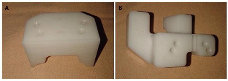
Figure 1 Patient specific blocks used in the present study (A: Femoral jig, B: Tibial jig).
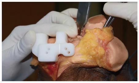
Figure 2 Tibial jig conforming to the proximal tibial anatomy and fiiting well to the bone.
This jig is used for insertion of the proximal tibial pins followed by use of the conventional proximal tibial jig.
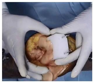
Figure 3 Femoral jig matching the contour of the anterior femoral cortex.
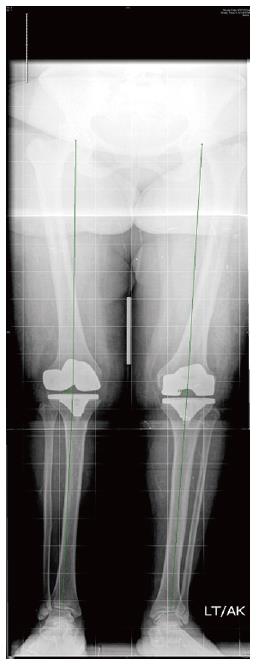
Figure 4 Postoperative weight bearing long leg radiograph measuring the hip-knee-ankle angle axis (mechanical axis).
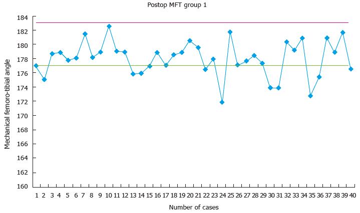
Figure 5 Scatter diagram depicting the distribution of the post-operative mechanical femoro-tibial angle (mechanical femoro-tibial angle) in the patient specific block group (group 1).
MFT: Mechanical femoro-tibial angle.
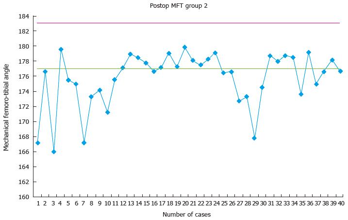
Figure 6 Scatter diagram depicting the distribution of the post-operative mechanical femoro-tibial angle (mechanical femoro-tibial angle) in the conventional instrument group (group 2).
MFT: Mechanical femoro-tibial angle.
- Citation: Vaishya R, Vijay V, Birla VP, Agarwal AK. Computerized tomography based “patient specific blocks” improve postoperative mechanical alignment in primary total knee arthroplasty. World J Orthop 2016; 7(7): 426-433
- URL: https://www.wjgnet.com/2218-5836/full/v7/i7/426.htm
- DOI: https://dx.doi.org/10.5312/wjo.v7.i7.426


