Copyright
©The Author(s) 2024.
World J Orthop. Sep 18, 2024; 15(9): 891-901
Published online Sep 18, 2024. doi: 10.5312/wjo.v15.i9.891
Published online Sep 18, 2024. doi: 10.5312/wjo.v15.i9.891
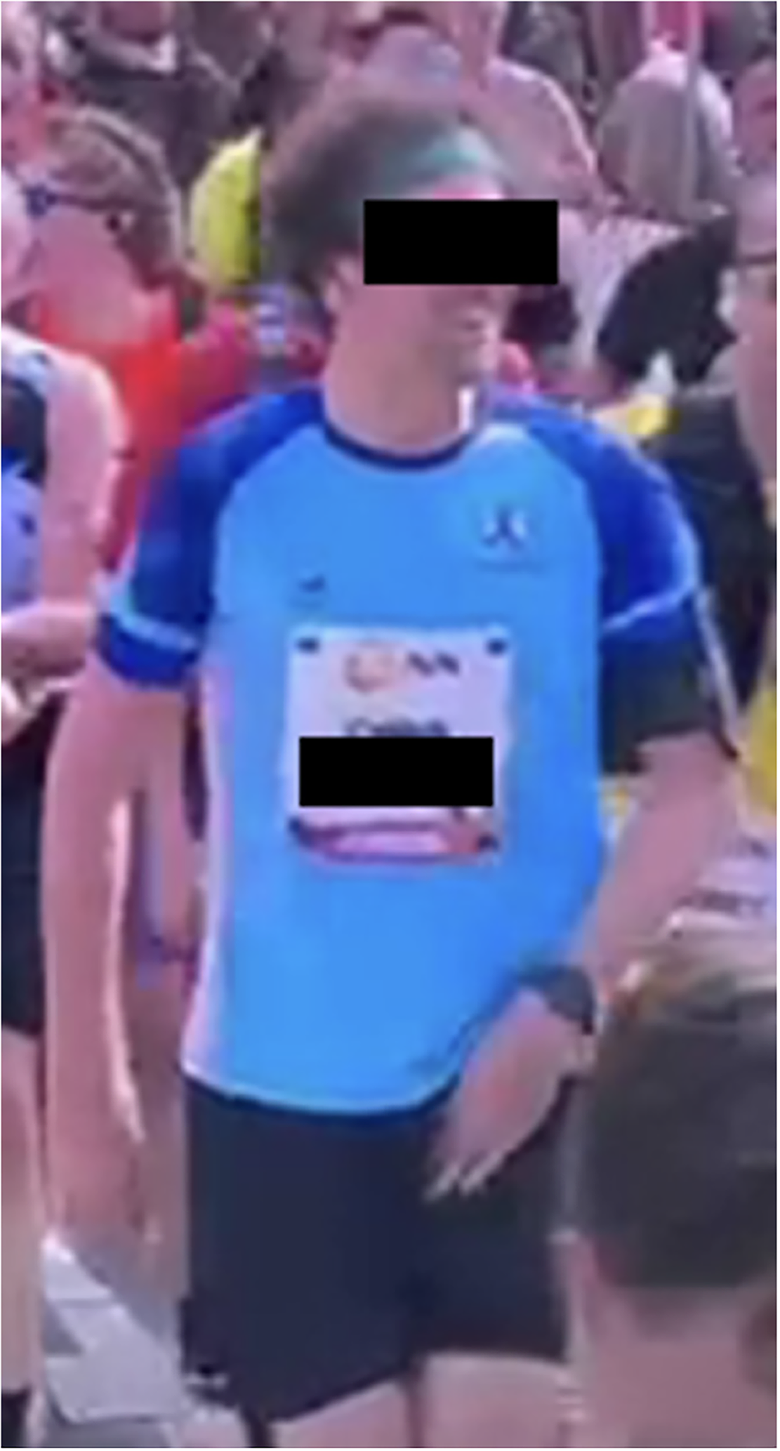
Figure 1 Clinical presentation.
Presentation at the time of completing the Marathon, with the fracture already present, where loading on the affected side was possible, but limited by pain. Particularly notable is the patient’s self-localization.
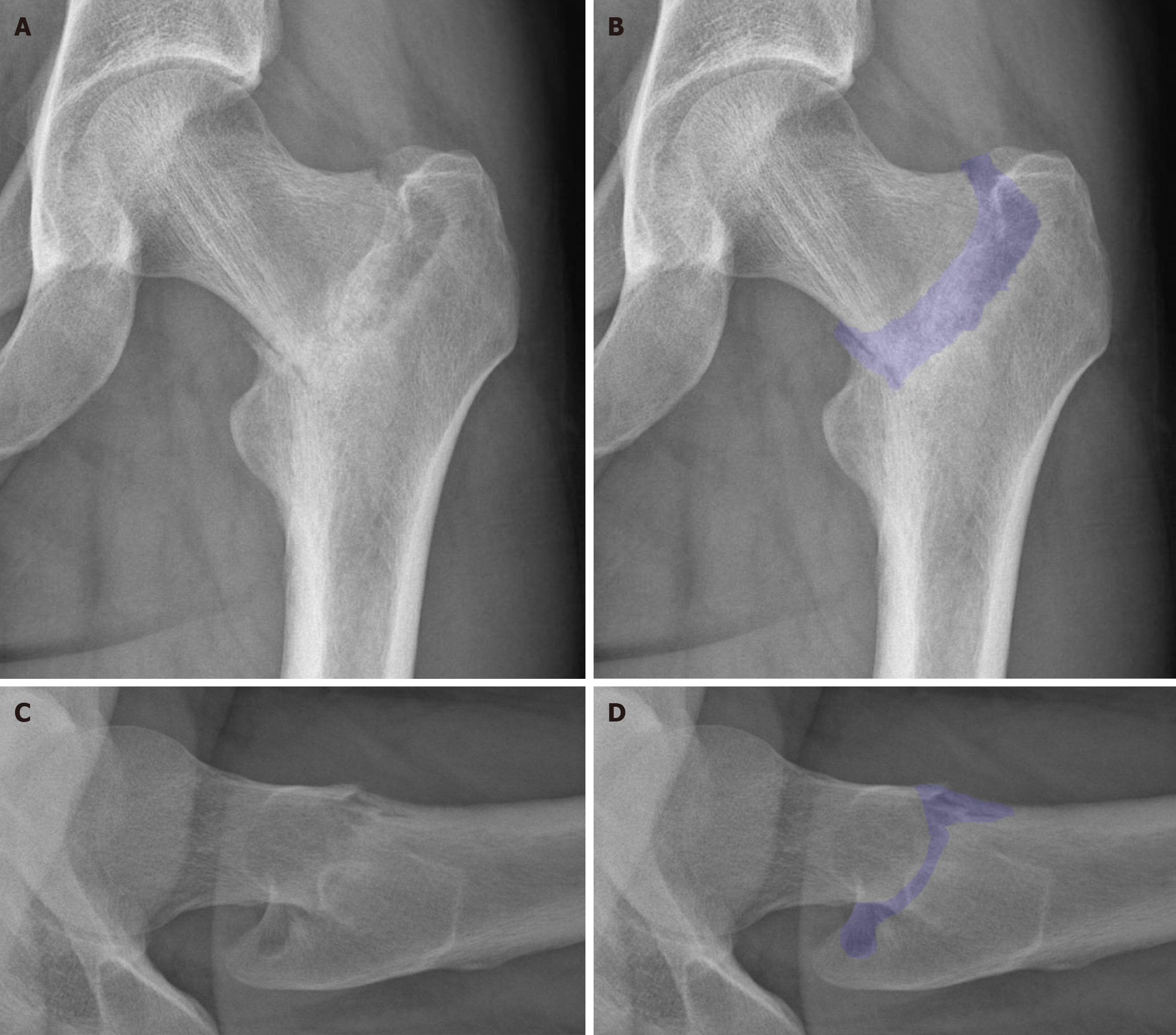
Figure 2 X-ray at presentation, coronal and lateral views.
This coronal X-ray of the left hip shows a complete lateral fracture of the left femoral neck, with shortening due to varus alignment of the fracture. The lateral X-ray of the left hip shows the external rotation and notably the fracture on the anterior side. A: Coronal X-ray without overlay; B: Coronal X-ray including an overlay, highlighting the fracture; C: Lateral X-ray without overlay; D: Lateral X-ray including an overlay, highlighting the fracture.
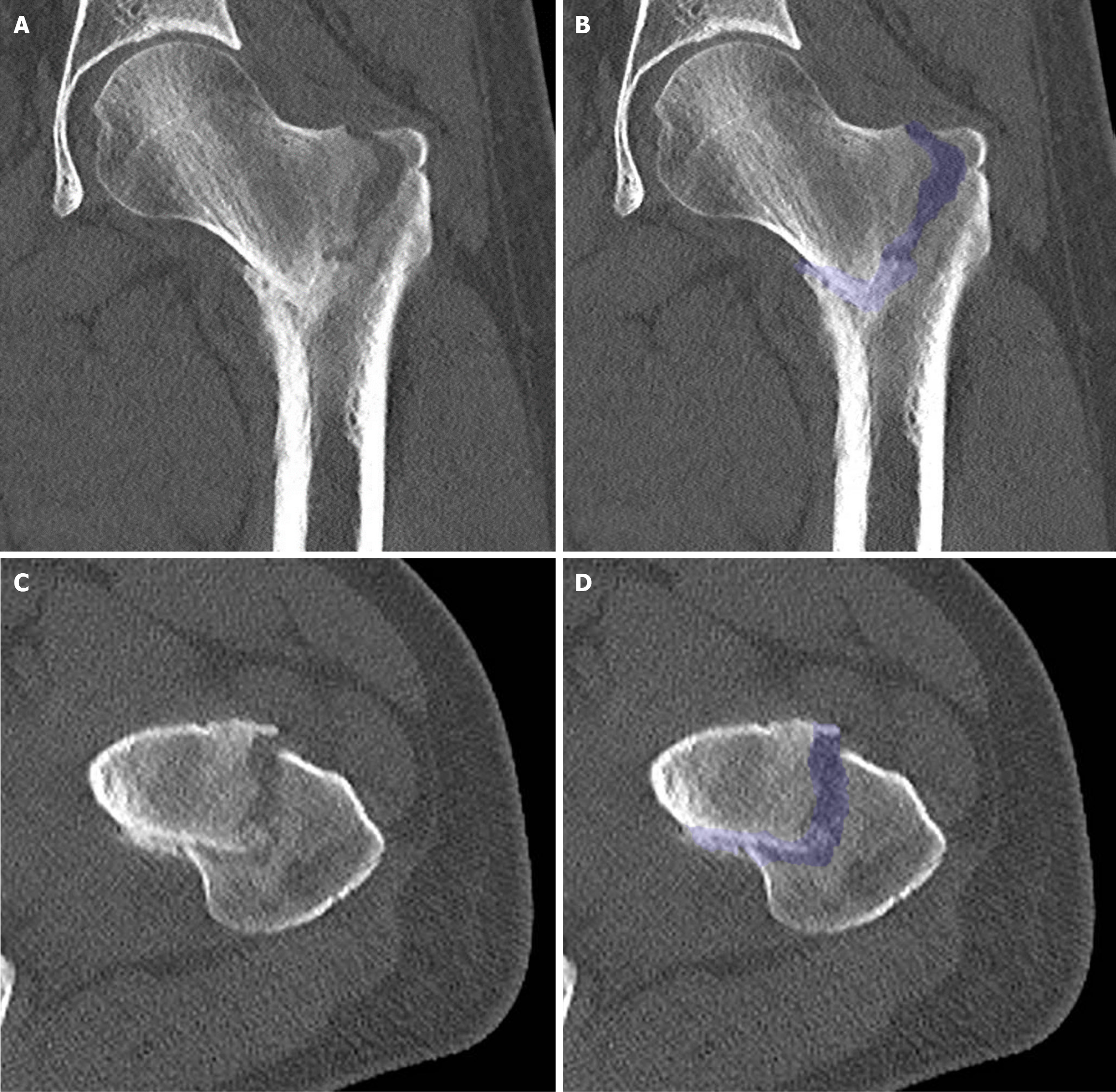
Figure 3 Computed tomography scan at presentation.
A: Coronal section without overlay; B: Coronal section including an overlay, highlighting the fracture; C: Transverse section without overlay; D: Transverse section with an overlay, highlighting the fracture. Additional imaging with computed tomography did not reveal evidence of pre-existing bone pathology, but confirmed significant impaction and malalignment. Furthermore, there were multiple signs of osteopenia in the left leg, most likely due to disuse over the preceding 3 weeks. Additionally, there was thickening of the periosteum on the medial side halfway down the femur, possibly due to altered force distribution. In the transverse section, external rotation is notably observed.
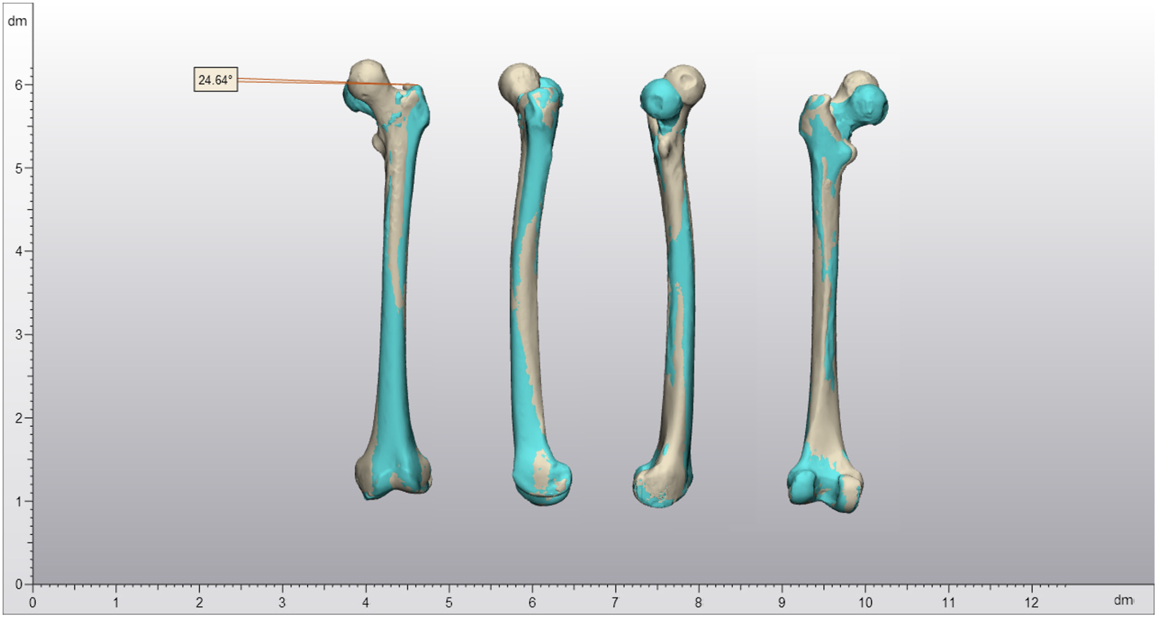
Figure 4 3D reconstruction of the fracture and malalignment at presentation.
This 3D reconstruction illustrates the malalignment: 24.6° of external rotation and 16.0 mm shortening due to varus alignment at the fracture site. From left to right: Images from anterior, lateral, medial, and posterior perspectives. The sand-colored reconstruction represents the contralateral side; cyan, the affected side.
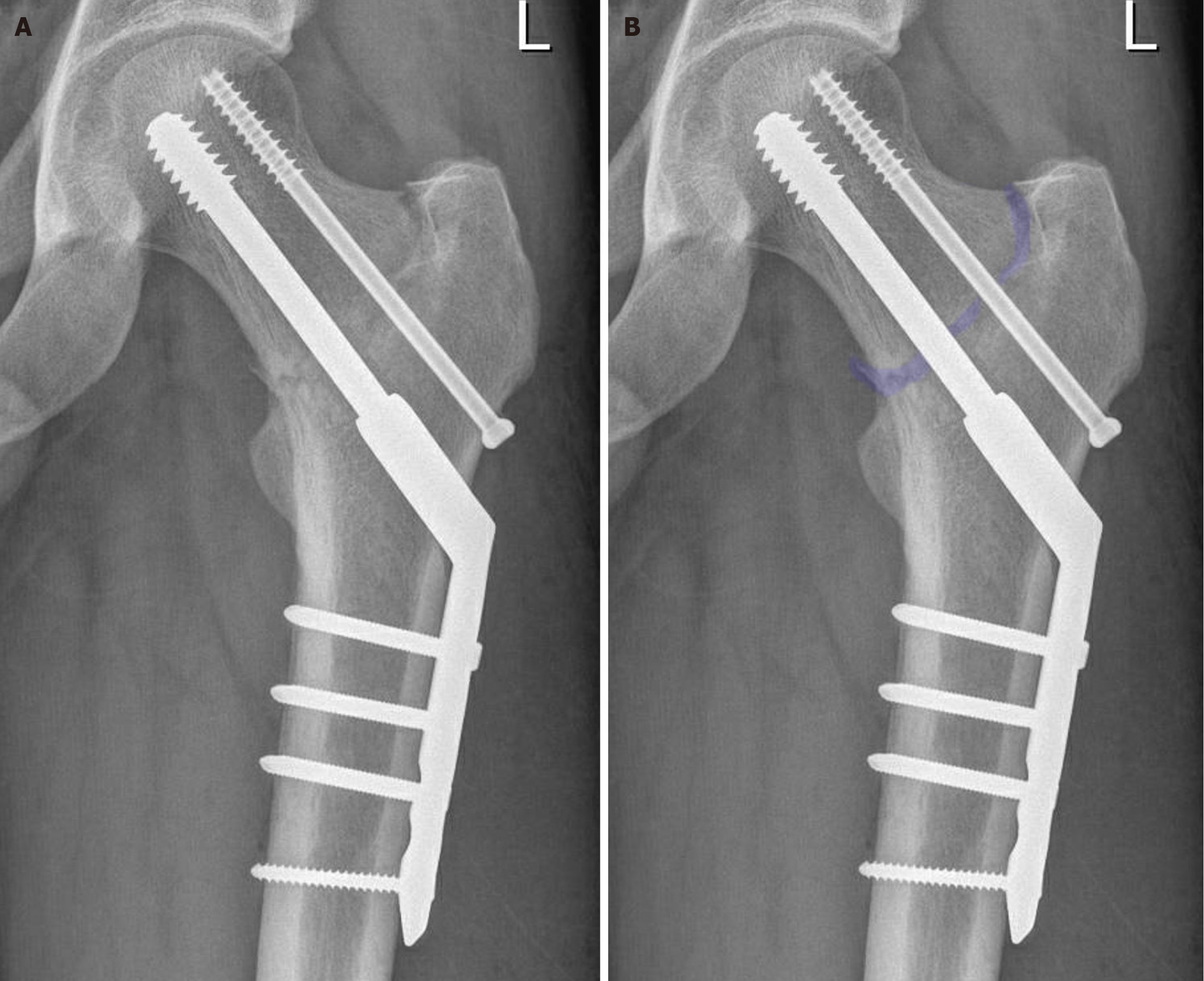
Figure 5 Position after bearing weight on postoperative day 1, coronal view.
The position post-operation and loading on day 1 was anatomically correct, with notably good results on the medial side, despite the delayed presentation. Due to uncertainty regarding underlying pathology, a four-hole dynamic hip screw including an anti-rotation screw was chosen. A: Corresponds to the picture without overlay; B: Includes an overlay, highlighting the fracture.
Figure 6 Position after bearing weight on postoperative day 1, lateral view.
The position post-operation and loading on day 1 was anatomically correct, with notably good results on the medial side, despite the delayed presentation. A: Corresponds to the picture without overlay; B: Includes an overlay, highlighting the fracture.
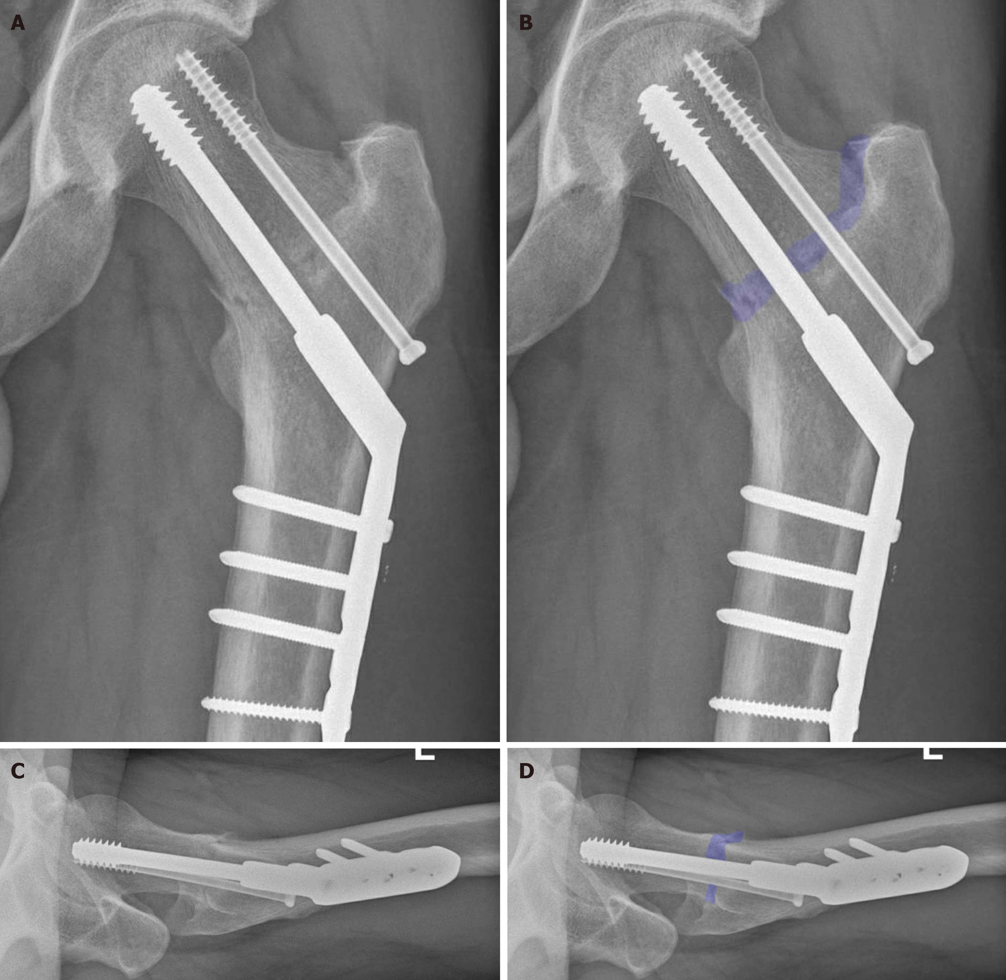
Figure 7 Position of osteosynthesis material at outpatient clinic follow-up.
A: Coronal X-ray without overlay; B: Coronal X-ray including an overlay, highlighting the fracture; C: Lateral X-ray without overlay; D: Lateral X-ray including an overlay, highlighting the fracture. During the outpatient clinic follow-up, the patient was almost free of complaints and the alignment was consistent with before. At this time, there were no convincing signs of bone remodeling, which is also not expected with this atypical fracture.
- Citation: Oudmaijer CA, Paulino Pereira NR, Visser D, Wakker AM, Veltman ES, van Linschoten R. Lateral femoral neck stress fractures: A case report. World J Orthop 2024; 15(9): 891-901
- URL: https://www.wjgnet.com/2218-5836/full/v15/i9/891.htm
- DOI: https://dx.doi.org/10.5312/wjo.v15.i9.891


