©The Author(s) 2015.
World J Cardiol. Nov 26, 2015; 7(11): 754-764
Published online Nov 26, 2015. doi: 10.4330/wjc.v7.i11.754
Published online Nov 26, 2015. doi: 10.4330/wjc.v7.i11.754
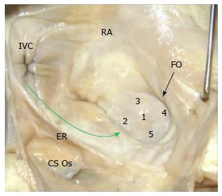
Figure 1 Fossa ovalis and transseptal punctures.
All of the 5 locations shown on the fossa ovalis (black arrow) are transseptal puncture possibilities, and the path of device delivery to the fossa ovalis is shown (green arrow). CS Os: Coronary sinus ostium; ER: Eustachian ridge; FO: Fossa ovalis; IVC: Inferior vena cava; RA: Right atrium.
Figure 2 Anatomy of fossa ovalis and Eustachian ridge related to transseptal punctures.
A: Inferior vena cava approach to transseptal punctures (green arrows); B: Image of fossa ovalis and Eustachian ridge (ER); C: Image of a patent foramen ovale in the fossa ovalis (two white arrows), with the ER adjacent to the fossa ovalis.
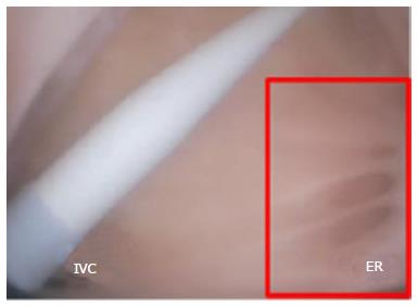
Figure 3 Catheter dilator and sheath in the right atrium.
Pectinated muscles border the Eustachian ridge (ER, red rectangle). IVC: Inferior vena cava.
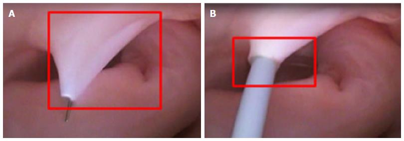
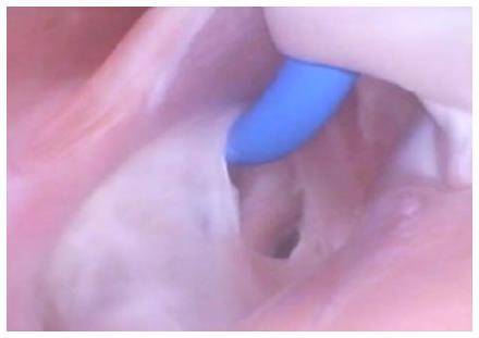
Figure 4 Fossa ovalis manipulation during transseptal punctures.
A: Deformation of the fossa ovalis at the point of needle puncture in the left atrium; B: Transseptal puncture at the time of dilator insertion, with deformation of the fossa ovalis (red oval) and a tight fit between the dilator and the fossa ovalis; C: Image of the septal ridge (red circle 1) around the fossa ovalis, the thin and highly compliant nature of the fossa ovalis (red circle 2), and the Eustachian ridge (red circle 3).
Figure 5 Tenting of the fossa ovalis.
A: View from the left atrium of the fossa ovalis at the point of needle puncture (red square); B: Simultaneous view from the right atrium at the point of needle puncture (red rectangle).
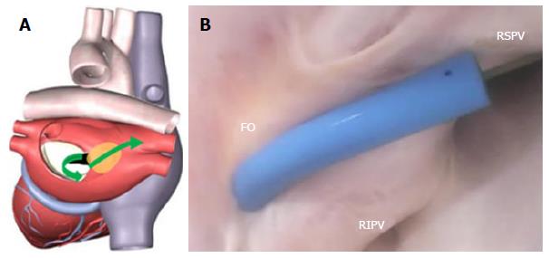
Figure 6 Fossa ovalis anatomy and device delivery for transseptal punctures.
A: Path of device delivery to the pulmonary vein originating from the fossa ovalis (green arrows); B: Left atrial sheath placement after a transseptal puncture, with a guidewire introduced into the right superior pulmonary vein (RSPV). FO: Fossa ovalis; RIPV: Right inferior pulmonary vein.
Figure 7 Tearing of the fossa ovalis.
Example of a potential complication as a result of catheter navigation performed in a swine, showing the fossa ovalis tearing due to excessive deflection force from a delivery sheath attempting to navigate into a pulmonary vein.
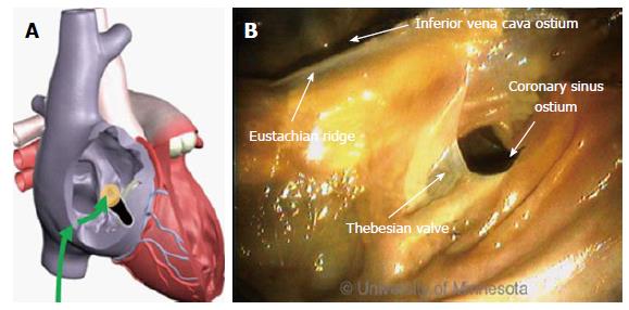
Figure 8 Coronary sinus and ablation procedures.
A: Device approach originating from the inferior vena cava into the coronary sinus ostium (green arrows); B: Regional anatomy in the area of the coronary sinus is bordered by the thebesian valve, including the inferior vena cava catheter introduction point.
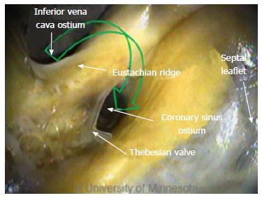
Figure 9 Deflection of devices in the coronary sinus.
Green arrow depicts the device approach originating from the inferior vena cava; devices in this region require a high degree of deflection.
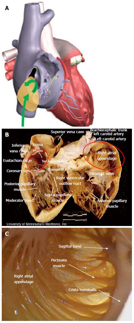
Figure 10 Right atrial appendage and transseptal punctures.
A: Approach to the right atrial appendage through the inferior vena cava (green arrows); B: Image shows the large size of the right atrial appendage (red oval, right side) and pectinated muscles (red oval, left side); C: Image of the pectinated muscles and thin tissue.
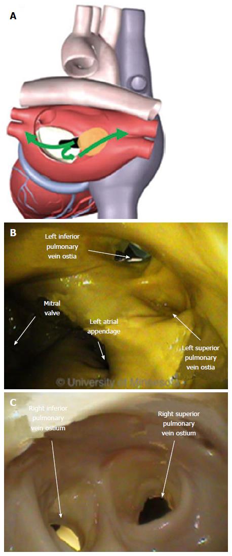
Figure 11 Pulmonary veins and ablation devices.
A: Directions of device introduction originating from the fossa ovalis into the left atrial pulmonary anatomy (green arrows); B: Image shows the left pulmonary vein ostium; C: Image of the right pulmonary vein.
Figure 12 Device placement in the right pulmonary veins.
A: Catheter sheath and the use of a guidewire for placement into the right superior pulmonary vein (RSPV, red oval); B: Introduction of the catheter tip at the pulmonary vein ostium (red oval); C: Retraction of the catheter sheath to the fossa ovalis (FO) and the introduction of a balloon catheter (red oval). RIPV: Right inferior pulmonary vein.
Figure 13 Device placements in the left pulmonary veins.
A: Catheter sheath and the use of a guidewire for placement into the left superior pulmonary vein (LSPV, green arrow); B: Placement of the guidewire into the pulmonary vein ostium (red oval); C: Introduction of the balloon catheter across the left atrium (green arrow).
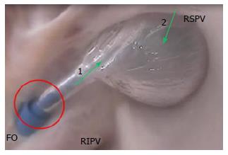
Figure 14 Balloon-based left atrial right superior pulmonary vein occlusion.
The sheath is retracted to accommodate the ablation catheter (red circle). The catheter orientation (green arrow 1) is not aligned with the pulmonary vein ostium orientation (green arrow 2). FO: Fossa ovalis; RIPV: Right inferior pulmonary vein; RSPV: Right superior pulmonary vein.
Figure 15 Left atrial appendage and device delivery.
A: Approach to the left atrial appendage from the fossa ovalis (green arrow); B: Position of the left atrial appendage relative to the mitral valve annulus and the presence of pectinated muscle; C: Position of the left atrial appendage relative to both the mitral valve and the left superior pulmonary vein.
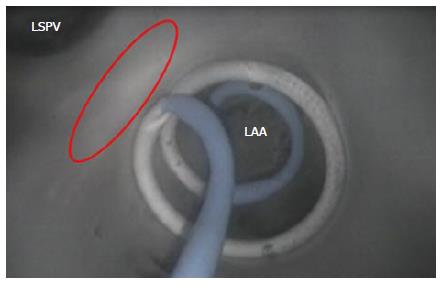
Figure 16 Device encircling the left atrial appendage.
Image shows the catheter shaft circulating around the left atrial appendage (LAA) ostium; the red oval depicts the ridge between the LAA and left superior pulmonary vein (LSPV).
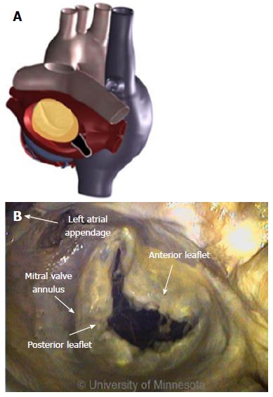
Figure 17 Mitral isthmus and roofline ablation.
A: Diagram shows the mitral valve in the left atrium; B: Various structures, including the mitral valve annulus, which serve as the starting point for creating a linear lesion in the mitral isthmus.
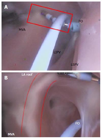
Figure 18 Focal ablation catheter.
A: Mitral isthmus lesion creation originating at the mitral valve annulus (MVA, red rectangle); B: Creation of a roofline linear lesion (red curved lines). FO: Fossa ovalis; LA: Left atrial; LIPV: Left inferior pulmonary vein; LSPV: Left superior pulmonary vein.
- Citation: Benscoter MA, Iaizzo PA. Visualization of catheter ablation for atrial fibrillation: Impact of devices and anatomy. World J Cardiol 2015; 7(11): 754-764
- URL: https://www.wjgnet.com/1949-8462/full/v7/i11/754.htm
- DOI: https://dx.doi.org/10.4330/wjc.v7.i11.754


