Copyright
©The Author(s) 2015.
World J Gastrointest Endosc. Jul 10, 2015; 7(8): 777-789
Published online Jul 10, 2015. doi: 10.4253/wjge.v7.i8.777
Published online Jul 10, 2015. doi: 10.4253/wjge.v7.i8.777
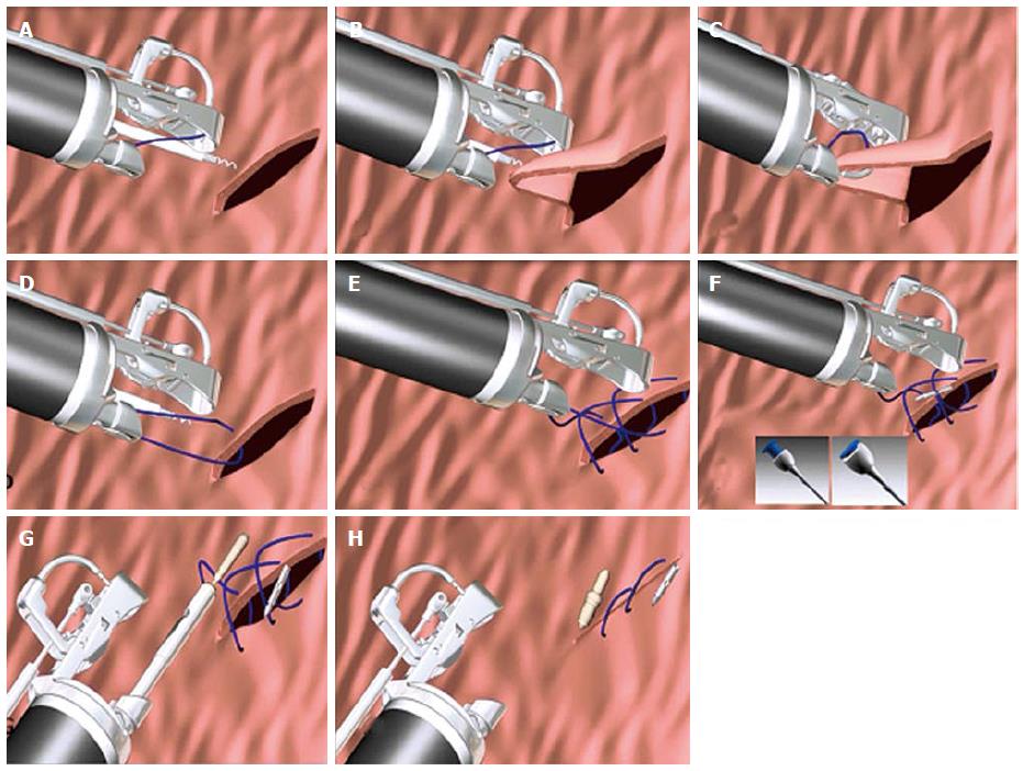
Figure 1 Steps involved in placing endoscopic sutures (Courtesy Apollo endosurgery Austin Texas).
A: Grasp the tissue using the tissue helix; B: Retract the tissue into the needle path; C: Drive the needle through the tissue; D: Open the arm and release the tissue; E: Repeat stitched as desired; F: Press the blue button to release the needle (T-fastener); G: Tighten and cinch; H: Repeat as desired.
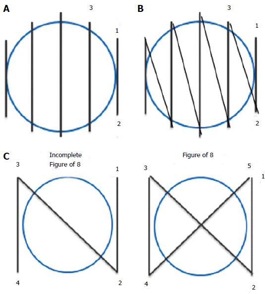
Figure 2 Types of suture pattern.
A: Interrupted suture; B: Running suture; C: figure of 8 suture.
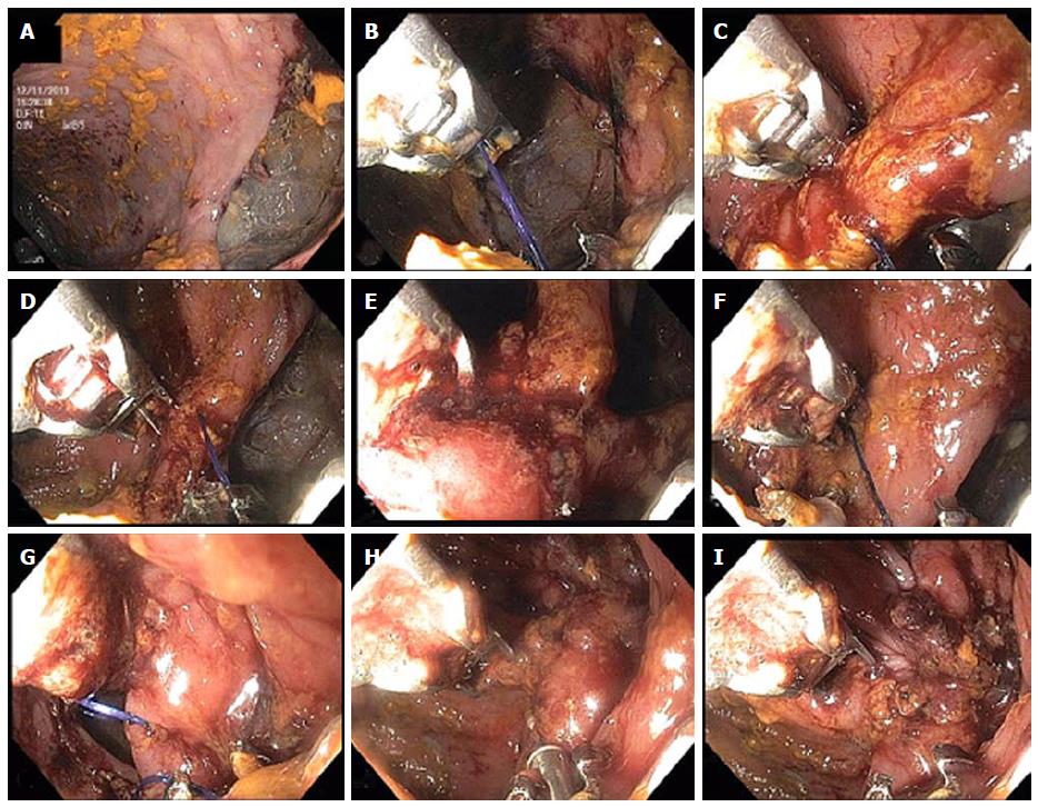
Figure 3 Closure of colonic perforation with endoscopic suturing device.
A: Initial tissue bites forming a running suture (B-E) starting at the inferior edge of the perforation and progressing towards the center; F: Tissue helix retractor is used to ensure deep tissue bite along the distal, superior edge of the perforation; G: Suturing has reached the superior edge of the perforation the edges of which are now being pulled together by the sutures; H: After tightening of the sutures closure of the perforation has been achieved and the cinch device is seen being deployed at the 6 o’ clock position of the image; I: Immediately after cinch deployment, the complete closure of the perforation is seen. Gastrograffin was injected through the scope that confirmed absence of leak (not shown).
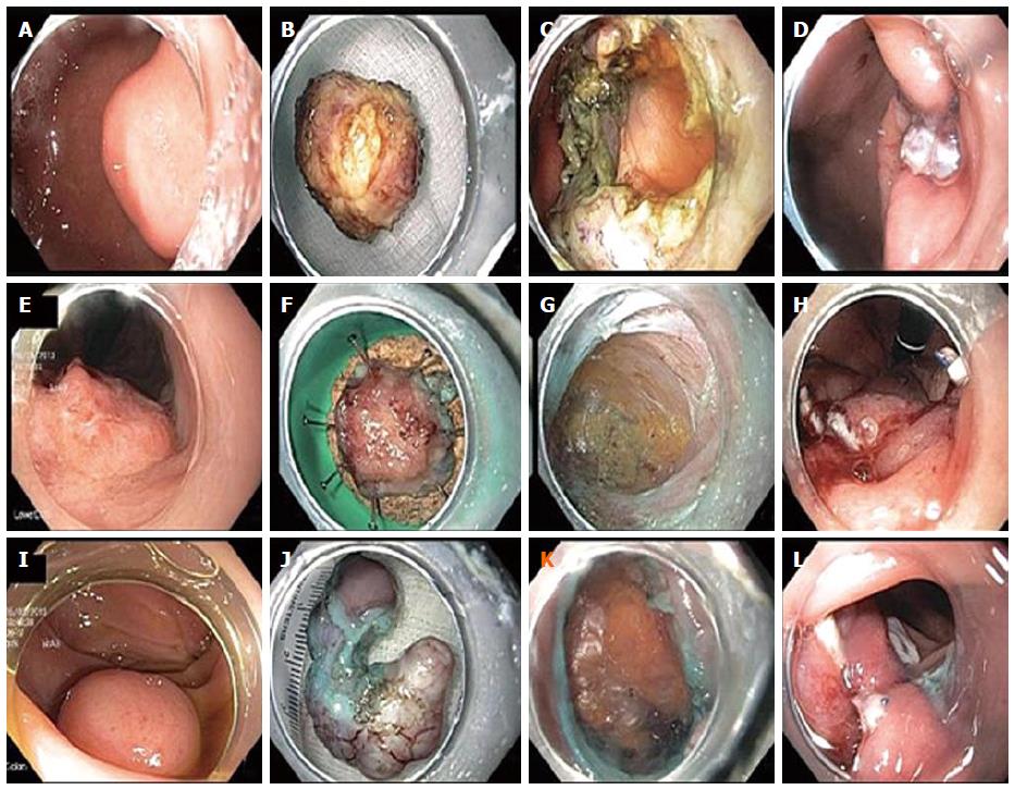
Figure 4 Closure of intentional full thickness perforations after subepithelial tumor removals with endoscopic suturing device.
A: Endoscopic image of gastric muscularis propria based subepithelial tumor; B: 2.5 cm schwannoma; C: Resection crater revealing transmural fat; D: Endoscopic sutured closure of defect; E: Endoscopic image of rectal carcinoma superficially extending to muscularis propria; F: 1.3 cm rectal low-grade adenocarcinoma; G: Resection crater demonstrating perirectal fat, circular muscle layer and longitudinal muscle layers; H: Endoscopic sutured closure of defect; I: Endoscopic image of sigmoid muscularis propria based subepithelial tumor; J: 3cm leiomyosarcoma; K: Resection crater demonstrating peritoneal fat; L: Endoscopic sutured closure of defect.
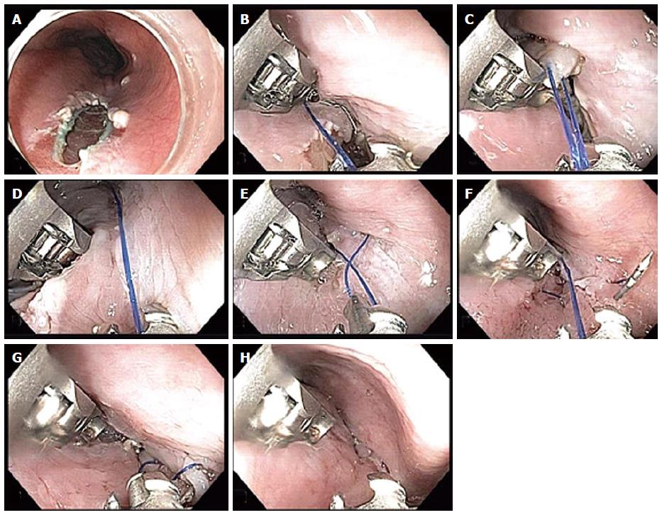
Figure 5 Closure of per oral endoscopic myotomy tunnel orifice with endoscopic suturing device.
A: Closure of peroral endoscopic myotomy (POEM) tunnel orifice in a posterior POEM with the tunnel opening at the 5 o’ clock position; B, C: We use a single running suture for closure starting at the distal, left margin of the defect as shown here. We attempt to penetrate mucosa and submucosa but not muscularis propria to avoid ischemia and pain or even possible injury to mediastinal structures; D: We proceed with suture placement through the right margin of the defect which is accomplished by torquing the endoscope as shown here; E: It is important to avoid having the running suture (here held by the needle onto the needle transfer catheter prior to loading it onto the needle driver) cross over the long suture leading to the start of the suture line which would then result in inability to properly deploy the cinch to the start or the suture line; F: The single running suture has been completed and has approximated the edges of the defect and the needle has been dropped in order to serve as a T-tag securing the suture at the proximal end of the defect; G, H: The cinch catheter is inserted over the long suture leading to the start of the running suture in the distal end of the defect, the suture is tightened and the cinch is deployed securing the suture at the start of the suture line in the distal end of the defect.
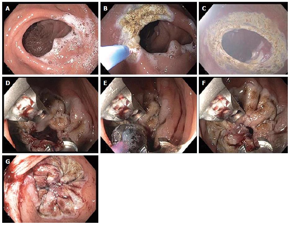
Figure 6 Endoscopic revision of gastrojejunal anastomosis in gastric bypass patient.
A: An enlarged gastrojejunal anastomosis is noted; B and C: Argon plasma coagulation was used around the stoma to ablate the mucosa and facilitate tissue fusion during the healing process; D: Two sutures were used obtaining circumferential tissue bites to achieve a purse-like closure of the stoma; E: A 10 mm controlled radial expansion balloon was dilated and placed through the stoma opening via the second channel of the double-channel therapeutic endoscope and then the sutures were tightened so that the final stoma diameter was approximately 10 mm in size; F and G: The balloon was then deflated and removed. A markedly diminished stoma orifice is seen at the end of the procedure.
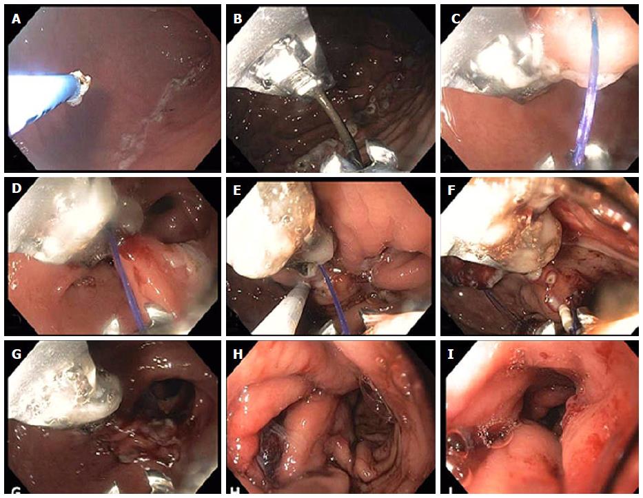
Figure 7 Endoscopic sleeve gastroplasty.
A: Initially argon plasma coagulation is used at a setting of 0.8 L 30 W, forced coagulation to mark the anterior and posterior extents of a corridor that will contain the outer sutures to be placed (as shown in the attached schematic (bites along the anterior wall, greater curvature and posterior wall); B: The suturing device is inserted and placement of the first running outer suture is begun as shown in figures C and D reducing the lumen along the greater curvature of the antrum; E: The helical tissue retractor is used through the second channel of the endoscope as seen in figure E to achieve deep, transmural if possible placement of the sutures and to facilitate suture placement in difficult locations; F: Insertion of the cinch device shown at the 6 o’clock position. The running suture can be seen at 7 o’clock prior to tightening; G: After tightening and cinching of the suture the lumen reduction forming the beginning of the endoscopic sleeve can be seen; H: Completion of the outer sutures showing marked lumen reduction; I: Completion of the inner row of sutures with final appearance of the endoscopic sleeve gastroplasty at the end of the procedure. A tight 3-4 cm tunnel is seen which extends from just distal to the fundus to approximately 3 cm proximal to the pylorus.
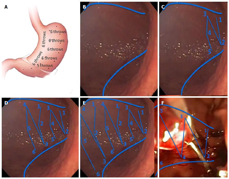
Figure 8 Suture placement needed to achieve endoscopic sleeve gastroplasty.
A: Schematic of the configuration of sutures used to achieve endoscopic sleeve gastroplasty. Initially 5 to 8 plication sutures are placed along the greater curvature in a distal to proximal direction, followed by placement of an inner row of 2 to 3 short anterior/posterior “retention sutures” that take some of the tension off the plication sutures; B: Using APC ablation two lines are made along the anterior and posterior wall that mark the outer borders of the plication sutures; C: The first plication suture is placed within 3 cm of the pylorus where due to the narrowing of the lumen results in a modified 5-point suture with the first bites placed on the anterior and posterior wall of the antrum while the 3rd, 4th and 5th bites are placed on the anterior wall, greater curvature and posterior wall; D, E: Subsequent plication sutures all have the same 6 point configuration (anterior wall, greater curvature, posterior wall, anterior wall, greater curvature, posterior wall); F: The inner row of retention sutures consists of sutures of sutures between the anterior and posterior wall a shown (Courtesy Apollo Endosurgery Austin Texas).
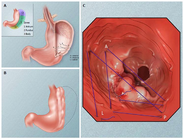
Figure 9 Illustration of the overall sleeve gastroplasty configuration achieved by placement of sutures as to achieve plication of the greater curvature of the stomach.
A: Endoscopic gastroplication pattern; B: Plicated stomach; C: Schematic of suture pattern (Courtesy Apollo Endosurgery Austin Texas).
- Citation: Stavropoulos SN, Modayil R, Friedel D. Current applications of endoscopic suturing. World J Gastrointest Endosc 2015; 7(8): 777-789
- URL: https://www.wjgnet.com/1948-5190/full/v7/i8/777.htm
- DOI: https://dx.doi.org/10.4253/wjge.v7.i8.777


